Variable distortion aberration image pickup device

a pickup device and distortion center technology, applied in the field of variable distortion aberration image pickup devices, can solve the problems of impossible off the center of the image frame, and inability to reproduce artificially distorted images whose distortion center coincides with a component of an obj

Inactive Publication Date: 2005-05-19
TAMRON
View PDF11 Cites 19 Cited by
  • Summary
  • Abstract
  • Description
  • Claims
  • Application Information

AI Technical Summary

Benefits of technology

[0024] In another aspect of the present invention, the distortion aberration conversion circuit is capable of displacing the center of distortion inside or outside the image.
[0029] Thus, in accordance with the present invention, the variable distortion aberration image pickup device attains an effect of varying distortion aberration of an image with the center of distortion aberration at any desired location either inside or outside the same, or more specifically, it attains an effect of developing and / or eliminating distortion aberration with its center at any desired location both inside and outside the image so as to vary the same.
[0030] Also, in accordance with the present invention, the device further provides a feature of varying distortion aberration with its center at any desired location either inside or outside an image, separately in individual directions, and more specifically, it attains an effect of creating an image of varied distortion aberration ratios from one direction to another with the center of distortion at any desired location both inside and outside the image.

Problems solved by technology

Allowing for the above-mentioned disadvantages in the prior art, the present invention is made to overcome them, and above all, one significant problem with the fish-eye lens is that the center of distortion always coincides with the center of the image, and hence, it is impossible to reproduce an artificially distorted image where its distortion center is the desired part of an object such as the nose of a person that is off the center of an image frame, depending upon the desired layout of components of the object or the image.
Although, as in the disclosure of Patent Document 1, it is possible to vary the distortion ratio from one direction of the image to another, a component of an object, such as the nose of a person, off the center of the image frame cannot be the distortion center in reproducing the artificially distorted image.
The technology disclosed in Patent Document 2 simply enables a user's choice of correcting or not the distortion aberration, and it is impossible to reproduce the artificially distorted image of which distortion center coincides with a component of an object, such as the nose of a person, off the center of the image frame.
Although the lookup table is used to compensate the distortion aberration in Patent Document 4, the distortion aberration compensation employed therein is performed based upon distances from the center of the image, and the disclosed technology does not enable a creation of an anamorphic image with the distortion center such as the nose of a person located off the center of the image frame.
Although the technology disclosed in Patent Document 5 permits the interpolating for any desired point of the data, it yet is not capable of creating an anamorphic image with the distortion center such as the nose of a person located off the center of the image frame.

Method used


Image

  • Variable distortion aberration image pickup device
  • Variable distortion aberration image pickup device
  • Variable distortion aberration image pickup device

Examples


embodiment 1

[0037] An exemplary variable distortion aberration image pickup device according to the present invention is designed to create a distortion aberration picture plane symmetric in respect to the center of symmetry and a distortion aberration compensation picture plane symmetric in respect to the axis of symmetry.

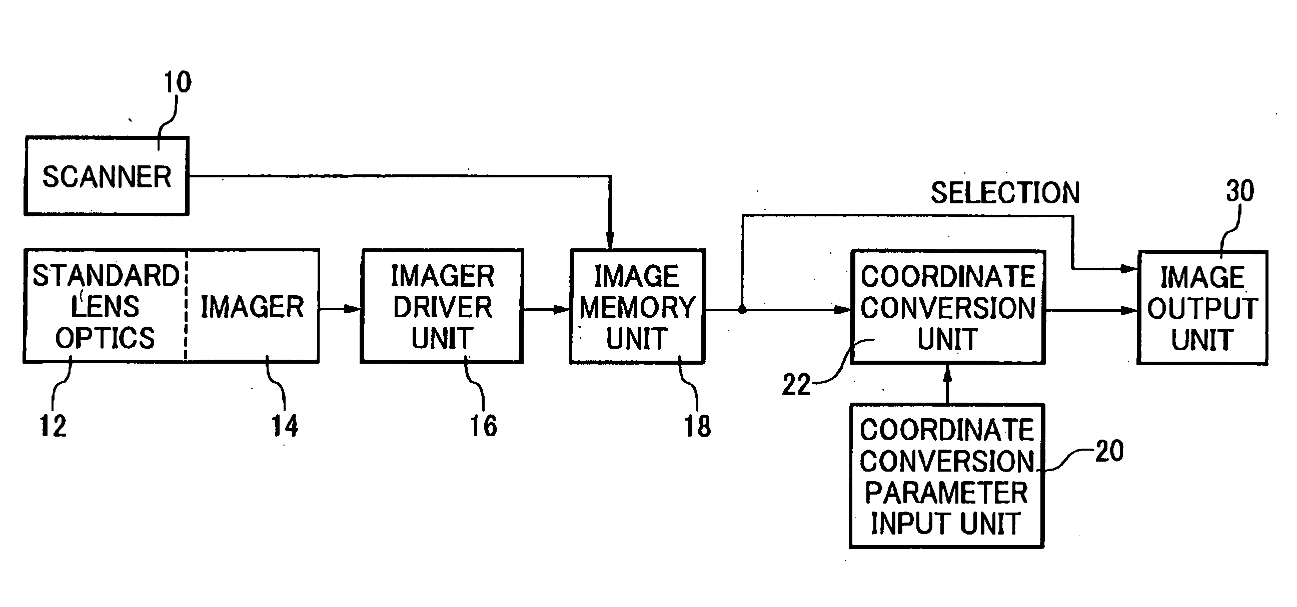
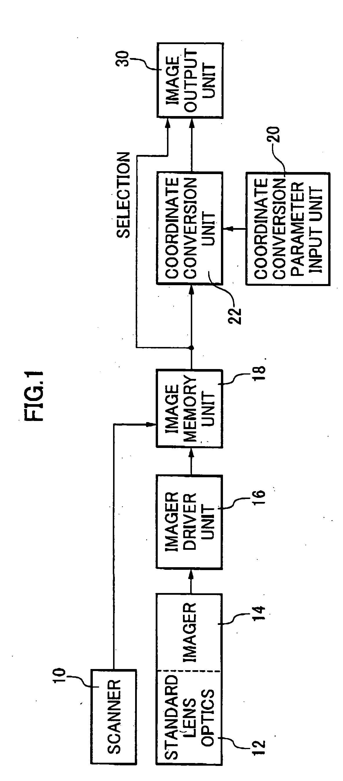
[0038] The signal processing is carried out through the scanning of an image of an object by a scanner 10 or the activation of an imager 14 with a standard lens optics 12 by an imager driver unit 16 so as to input an image signal to an image memory unit 18. A coordinate conversion unit 22 receives the image signal through the image memory unit 18 and also receives coordinate conversion parameters trough a coordinate conversion parameter input unit 20. The coordinate conversion unit 22 uses the coordinate conversion parameters to process the image signal by varying distortion aberration therein and produces the revised image signal to an image output unit 30. The image signal...

embodiment 2

[0063] An additional preferred embodiment of the present invention is designed to produce an image symmetric about a point other than the center of distortion, and hence, the resultant image on the picture screen is different from an image compensated for the distortion aberration symmetrically in respect to the center of distortion. In other words, the image eventually obtained is that which has the image dislodged from a given reference center as desired with varied distortion aberration ratios from one direction to another, or compensated for distortion aberration from the reference center with varied displacement ratios from one direction to another.

[0064] In this embodiment, the maximum distortion ratio K (mm) from the given reference center as desired is varied from one direction to another. The maximum distortion ratio K (mm) between any set of the adjacent directions can be interpolated by some well-known mathematical method.

embodiment 3

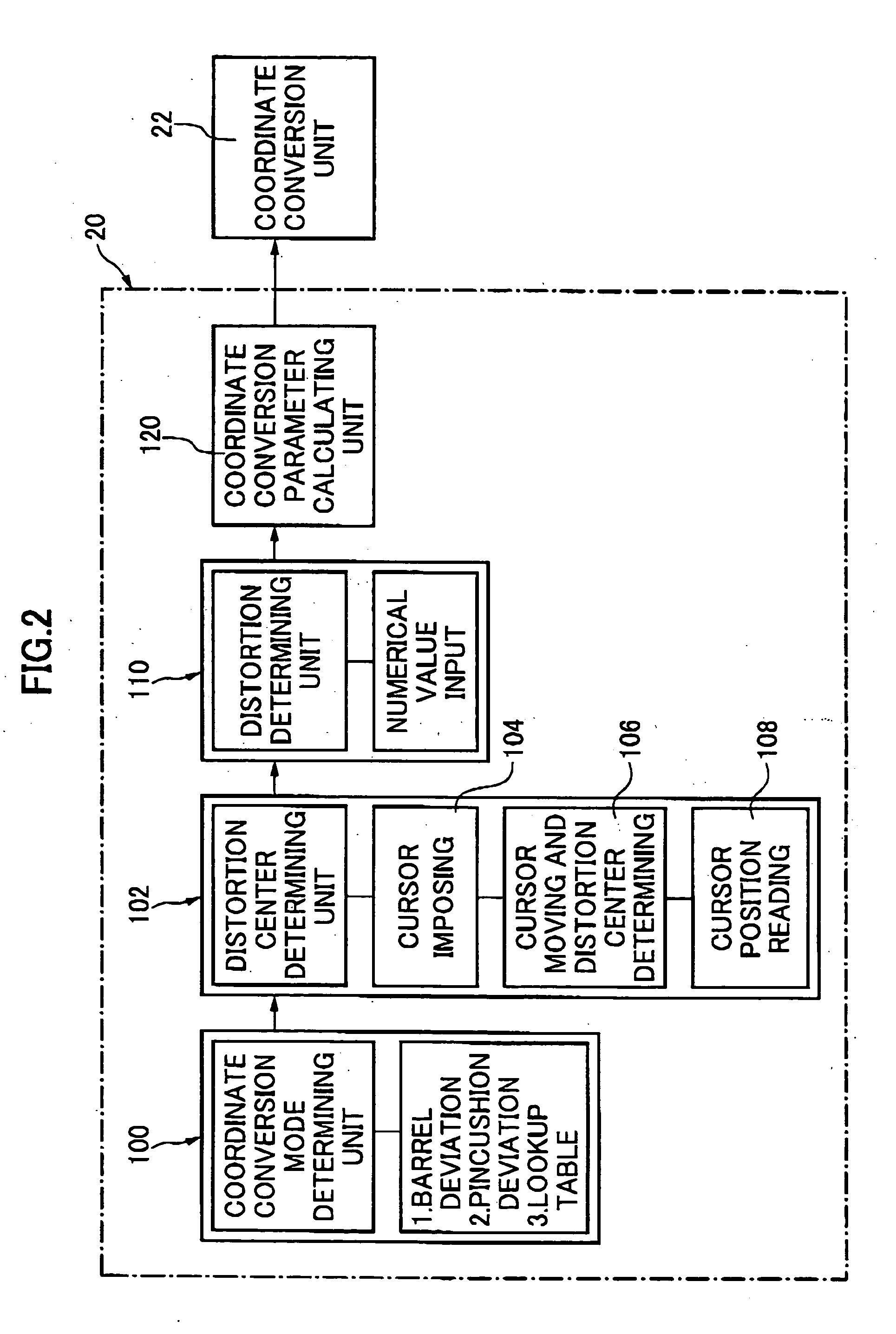
[0065] In the aforementioned Embodiments 1 and 2, the coefficient used to dislodge the original coordinates is determined based upon the sine curve. In this additional embodiment, however, such a coefficient used to dislodge the original coordinates is determined on the square function curve, or curves or lines preprogrammed and contained in the lookup table.

[0066] As has been described, one of the objects of the present invention is to facilitate to produce a funny and enjoyable image from an original image without distortion aberration by artificially developing distortion aberration with its center at any location in the image. In addition, the invention attained in such a manner uses a simplified image pickup device to enable the original image with distortion aberration to be transformed in a perfect image without distortion aberration. Moreover, successively varying the center of distortion and / or the degree of distortion for amusement permits the resultant image to have funn...


PUM


Abstract

The present invention is directed to a variable distortion aberration image pickup device that is capable of varying distortion aberration with its center at any desired point either inside or outside an image where, specifically, distortion aberration is effectively developed and / or eliminated with the distortion center at any desired point both inside and outside the image as desired, and such an image pickup device is also capable of varying distortion aberration with its center at a desired point either inside or outside the image, separately in individual directions, where specifically an image is processed so as to have distortion aberration with its center at any desired point both inside and outside the image, with varied distortion ratios from one direction to another. For that purpose, the variable distortion aberration image pickup device is comprised of a photograph lens, two-dimensional opto-electronic feedback elements, and a distortion aberration conversion circuit that receives output image signals from the two-dimensional opto-electronic feedback elements to dislocate a desired point of an image in some direction(s) from the given center of distortion.

Description

FIELD OF THE INVENTION [0001] The present invention relates to a variable distortion aberration image pickup device that is capable of both artificially distorting an image of an object where the image is edited to reproduce a barrel-shaped swelled object or reversely a pincushion-shaped squeezed object so that the resultant image is funny and enjoyable to see and artificially correcting an anamorphic image of an object to result in the image without distortion, precisely reproducing the object. BACKGROUND ART [0002] As for the prior art image pickup devices capable of distorting an object image omnidirectionally with varied distortion ratios depending upon a distance from a predetermined position or capable of correcting an anamorphic image of an object to create the image without distortion, there have been proposed those as mentioned below. [0003] One proposed method in the prior art is varying a magnification / reduction ratio between the primary and secondary scanning directions ...

Claims


Application Information

Patent Timeline
Patent Type & Authority Applications(United States)
IPC IPC(8): G06K9/40G06T3/00G06T5/00H04N1/387H04N5/232
CPCG06T5/006
Inventor NARITA, YOSHINORI
Owner TAMRON
Why Eureka
Try Eureka