Hole cutter and method for producing

a technology of hole cutter and cutter, which is applied in the direction of manufacturing tools, tool workpiece connection, transportation and packaging, etc., can solve the problems of relatively expensive, and insufficient performance of hole cutter for deeper holes and harder materials, and achieve the effect of low cost of hole saw

Inactive Publication Date: 2005-05-19
M K MORSE COMPANY THE
View PDF36 Cites 56 Cited by
  • Summary
  • Abstract
  • Description
  • Claims
  • Application Information

AI Technical Summary

Benefits of technology

[0009] The present invention overcomes at least one disadvantage of prior art machine tools. These and other advantages are provided by a hybrid machine tool identified as a hole cutter assembly combining the low cost of a hole saw with the performance of an annular cutter. The machine tool comprises a monolithic cutter ring member comprising a plurality of cutting teeth spaced circumferentially around a first end thereof, and a plurality of flutes, each flute formed in an outer cylindrical surface of the cutter ring member and extending from the first end to a second end of the cutter ring member. The machine tool further comprises a body member comprising a cylindrical portion having a first end and a second end, wherein the first end of the body member is fixably attached a second end of the cutter ring member and the second end of the body member comprises a top portion formed generally perpendicular to a longitudinal axis of the cylindrical member.

Problems solved by technology

While hole saws have proven to operate in a generally satisfactory manner for relatively shallow holes and softer materials, their performance is often inadequate for deeper holes and harder materials, especially when a large number of holes need to be cut.
A problem with the prior art monolithic annular cutter is that it is relatively expensive.
The high speed steel is a premium material, which is expensive.
Deeper holes require longer annular cutters, which requires more material and more labor in machining and grinding.
Due to the expense of the annular cutters, they are limited in their use to relatively expensive machines such as the magnetic base drills, etc.
While these tungsten carbide teeth are particularly suitable for cutting rails and the like; the proper positioning, attaching, and machining of 4, 8, 12 etc. tungsten carbide tips can add significant cost to the production of the tool—especially in tooling required to properly position the tungsten carbide tips for attachment to the annular cutter body.

Method used


Image

  • Hole cutter and method for producing
  • Hole cutter and method for producing
  • Hole cutter and method for producing

Examples


first embodiment

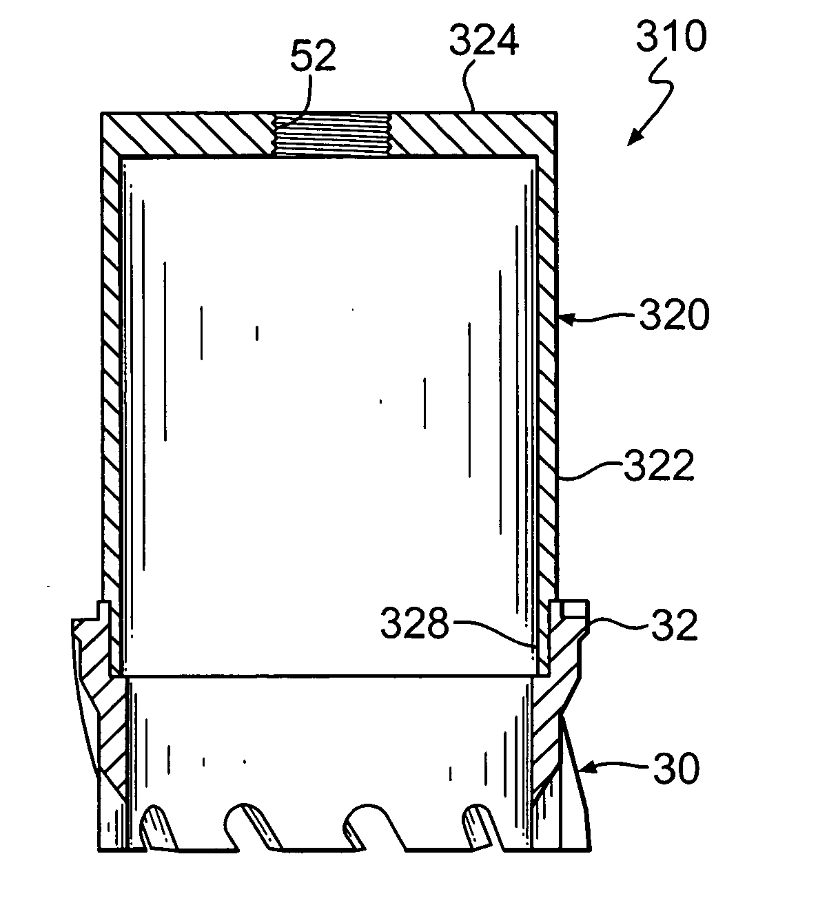
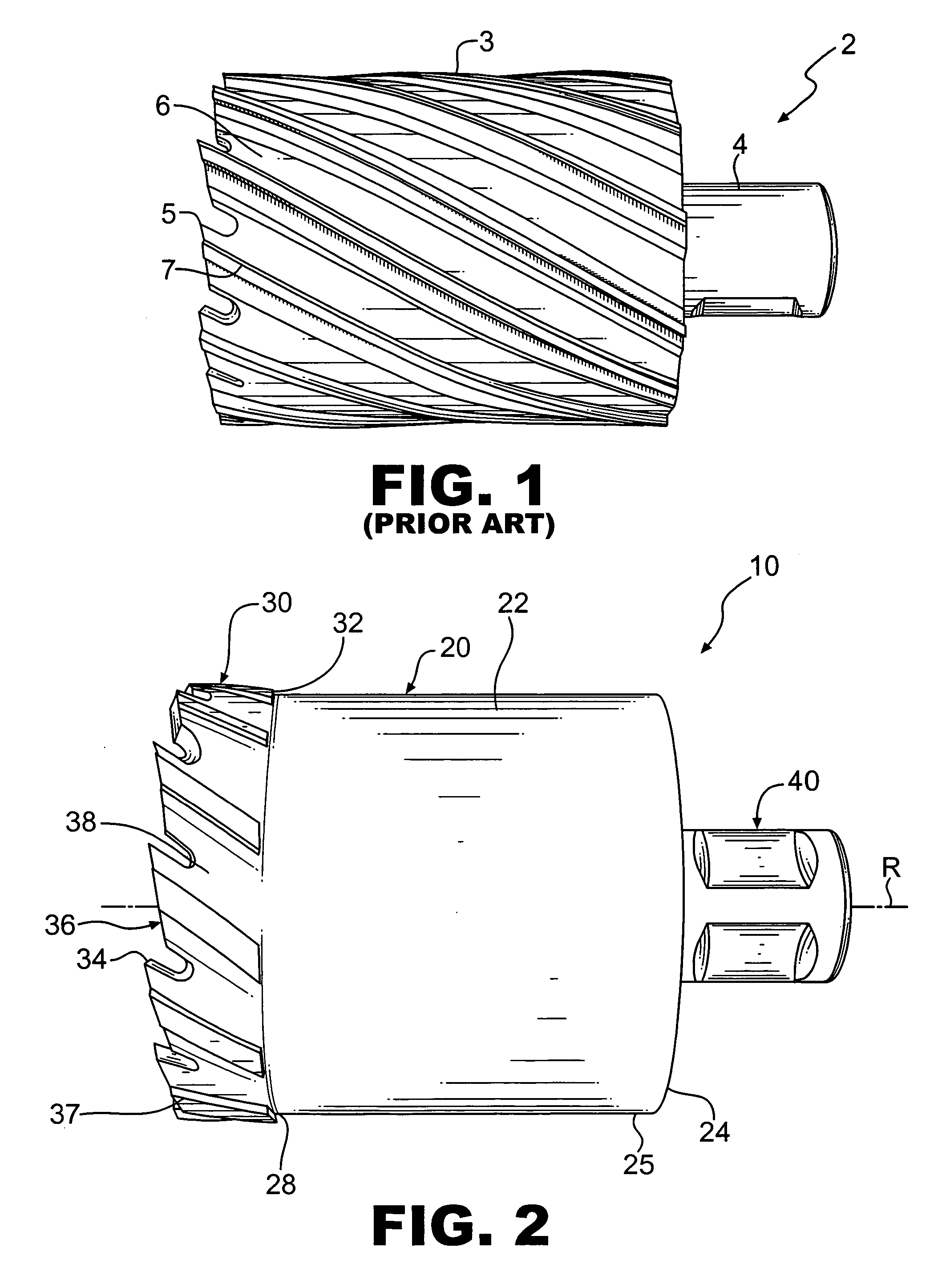
[0025] Referring to FIG. 2, the hole cutter assembly 10 of the present invention is shown. The hole cutter assembly 10 comprises a carrier body 20 and a cutter ring 30. The carrier body 20 comprises a cylindrical portion 22 and a top portion 24. The cylindrical portion 22 having a first end 28 and a second end 25. The top portion 24 typically extends radially inward from the second end 25 of the cylindrical portion 22 of the body 20. The cutter ring 30 is similar to the cutting end of the prior art annular cutter 2. The cutter ring 30 comprises a plurality of axially projecting teeth 34 from a first end 36 of the cutter ring 30. A second end 32 of the cutter ring 30 is fixably attached to the first end 28 of the cylindrical portion 22 of the carrier body 20. A plurality of flutes 38 and cutting edges 37 are formed in the outer circumferential surface of the cutter ring 30 and extend from the first end 36 of the cutter ring 30 to the second end 32 of the cutter ring 30. Optionally, a...

second embodiment

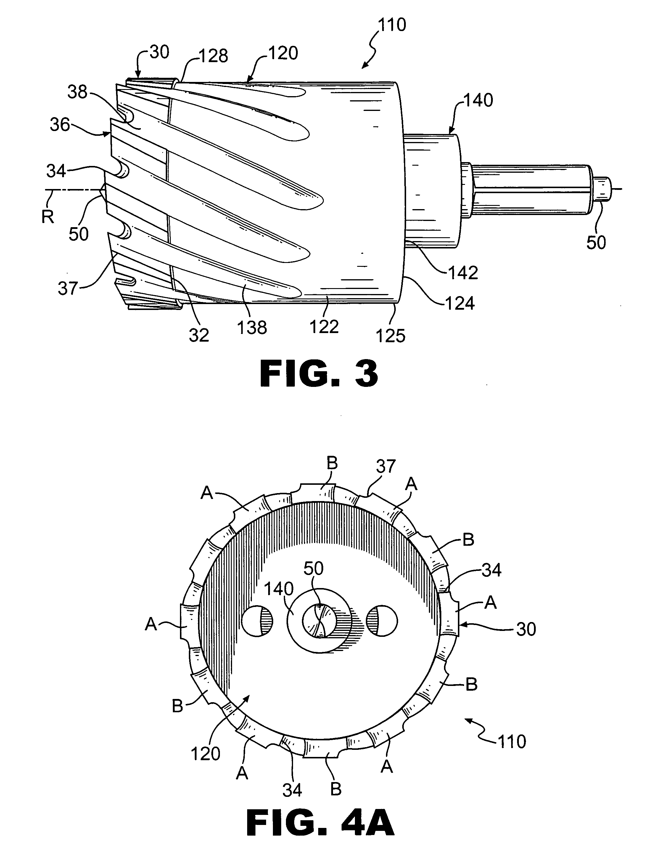
[0026] the invention is shown in FIG. 3. The hole cutter assembly 110 is shown with a hole saw style arbor 140. The top portion 124 of the carrier body 120 may have a threaded aperture (not shown) to receive a threaded end portion 142 of the hole saw style arbor 140. Arbor 140 is of the type typically used for standard hole saws and includes a pilot bit 50 attached to the arbor 140. The pilot bit 50 extends along the rotational axis R of the hole cutter assembly 110 and protrudes from the cutter ring 30 to guide the hole cutter assembly 110 during cutting. Although a pilot bit 50 is shown, the invention is not intended to be limited to a particular center configuration, alternative known configurations such as a spring loaded center pin (not shown), a solid shank, and any other known configurations are also contemplated. It is also contemplated that no guide or center member is needed for some applications and uses of the present invention. As previously discussed, flutes 138 are sh...


PUM

PropertyMeasurementUnit
axial lengthaaaaaaaaaa
temperatureaaaaaaaaaa
speedaaaaaaaaaa

Abstract

A hole cutter machine tool combines the characteristics and properties of a low-cost hole saw with the speed and performance of an annular cutter. The hole cutter comprises a cutter ring portion similar to an end portion of existing annular cutters with a carrier portion similar to the cup of a hole saw. In one embodiment the hole cutter has a threaded aperture which enables use with a standard hole saw arbor or with a replaceable arbor having an annular cutter shank. An embodiment of the method of making the hole saw includes a joining process in which the cutter ring is simultaneously attached to the carrier portion and heat treated.

Description

[0001] This application claims the benefit of U.S. Provisional Patent application Ser. No. 60 / 506,320, filed Sep. 26, 2003, and herein incorporated by reference.TECHNICAL FIELD [0002] The present invention relates to a machining tool and, more particularly, to a hole cutter machine tool which combines the characteristics and properties of a low-cost hole saw with the speed and performance of an annular cutter. BACKGROUND OF THE INVENTION [0003] Hole saws and annular cutters are machine tools used in drilling operations to cut a hole of a desired size. Hole saws and annular cutters remove a ring of metal leaving a central core or plug which can be removed as one piece. This enables faster hole drilling and requires less energy as only the perimeter is cut as compared to a standard twist drill which requires the entire hole to be reduced to chips. [0004] A hole saw is typically adapted to be used with a drill press or power drill that allows a user to make circular cut-outs in a mater...

Claims


Application Information

Patent Timeline
Patent Type & Authority Applications(United States)
IPC IPC(8): B23B51/04
CPCB23B51/0406B23B51/0426B23B51/0473B23B2222/32B23B2226/18Y10T408/895B23B2240/08B23B2240/16B23B2251/14B23B2270/30B23B2226/31B23B51/04
Inventor BYRLEY, DAVIDSAVASTANO, KEITH
Owner M K MORSE COMPANY THE
Why Eureka
Try Eureka