Joint member and joint connector for wire harness

a technology of joint connector and wire harness, which is applied in the direction of unstripped conductor connection apparatus, coupling device connection, laminating printed circuit board, etc., can solve the problems of difficult to reduce the thickness of the joint connector, the obstacle of disposing of the wire harness, and the large thickness of the entire joint member, so as to reduce the thickness of the joint member and reduce the amount of protruding joint member

Inactive Publication Date: 2005-05-19
AUTONETWORKS TECH LTD +2
View PDF8 Cites 9 Cited by
  • Summary
  • Abstract
  • Description
  • Claims
  • Application Information

AI Technical Summary

Benefits of technology

[0011] The present invention has been proposed in view of the above problems. One of objects of the present invention is to reduce the thickness of the joint member, and thus, to reduce the protrusion amount of the joint member when the joint member is wound around a wire harness.
[0012] Another object of the present invention is to provide a joint connector for a wire harness which can be made thin and is suitable for short-circuiting electric wires contained in a wire harness with each other.

Problems solved by technology

As a result, the thickness of the entire joint member is considerably large.
Accordingly, when the joint member is wound around a wire harness, the entire joint member largely protrudes to the outside in the diameter direction from the main body portion of the wire harness, and may become an obstacle for disposing the wire harness.
However, in the case of the joint connector described in JP-A-8-079948 above, it is difficult to reduce thickness of the joint connector, i.e., to reduce the height of the joint connector, because of which the joint connector when wound around the wire harness could stick out greatly.

Method used


Image

  • Joint member and joint connector for wire harness
  • Joint member and joint connector for wire harness
  • Joint member and joint connector for wire harness

Examples


first embodiment

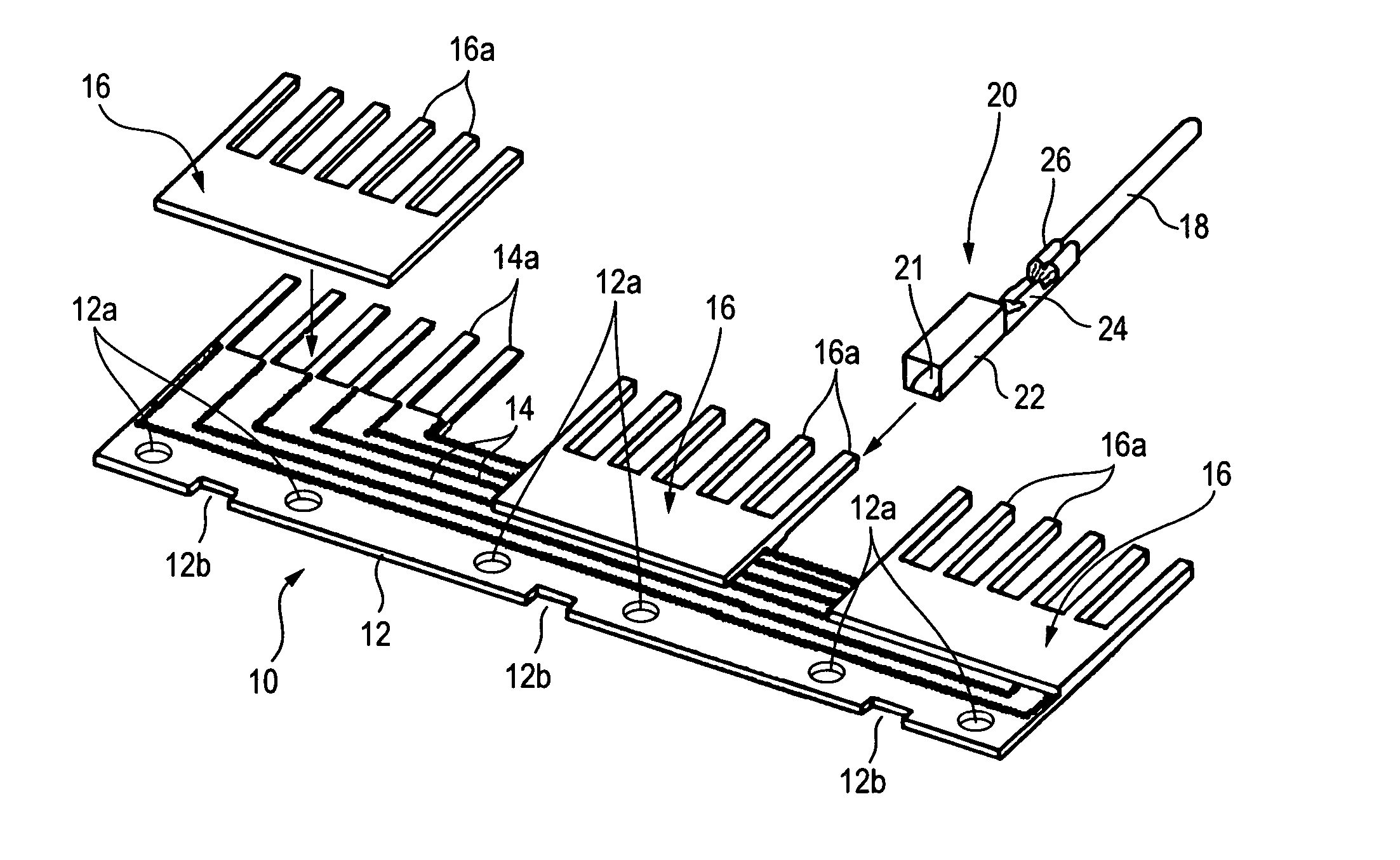
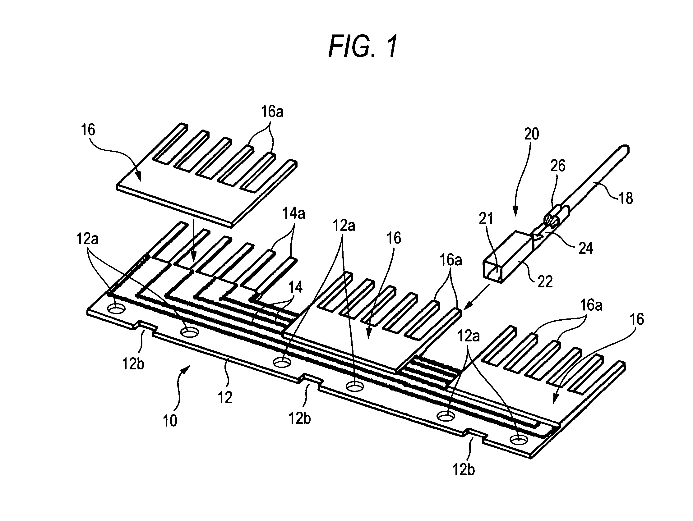
[0075]FIG. 1 shows an example of a joint member 10 according to the present invention, the joint member 10 having a flexible printed circuit substrate. The joint-member 10 shown in the figure is a base material 12 made of a thin insulating material extending in one direction, on which a conductor pattern 14 is printed. The conductor pattern 14 includes protruding portions 14a, which protrude outward from the edge portion extending in the longitudinal direction of the joint member 10 and constitutes joint-side terminals, and a connection circuit for electrically connecting between specified protruding portions 14a.

[0076] In the example shown in the figure, protruding portions 14a for 3 groups (total 18), in which one group includes 6 portions, are formed. Also, in each group, formed in the edge portion of the base material 12 opposite the protruding portions 14a are notches 12b. And formed in two positions sandwiching the notch 12b are through-holes 12a.

[0077] Further, in the joint...

second embodiment

[0108] Next, the joint connector having the joint-side insulation housing will be described.

[0109] In FIG. 5, an example, in which the joint-side terminals are directly fitted with the wire-side terminals 20 held by the wire-side insulation housing 30, is shown. Joint connectors shown in FIG. 16 and FIG. 17 are arranged so that a plurality of joint-side insulation housing 70 for holding a plurality of joint-side terminals, which are evenly aligned (in the figures, the terminal component pins 66 of the joint member 60 shown in FIG. 9) are provided, and with these joint-side insulation housings 10, the wire-side insulation housings 30 corresponding to the housings 70 are fitted.

[0110] As shown in FIG. 18, each of the joint-side insulation housings 70 is provided so that, in the mid-portion in the axial direction thereof (in the figure, right-left direction), a pin press-in hole 71, which is capable of being pressed-in by the respective terminal component pins 66, is formed, and by pr...

third embodiment

[0146] the present invention will be described first, with reference to FIGS. 41-45.

[0147] The joint connector shown in these drawings includes wire-side terminals 120 fixed respectively to the ends of each electric wires 118 which form a wire harness, an insulation housing 130 which holds the plurality of wire-side terminals 120, and a plurality of short-circuit members 114.

[0148] The wire-side terminal 120 exemplarily shown in these drawings includes, closer to its tip end, a box-like female contact 122 which accepts a spring contactor 121, and behind this, a conductor barrel 124 pressed to a conductive portion of the corresponding electric wire 118 and an insulation barrel 126 pressed to an insulation sheath of the electric wire 118. The wire-side terminal 120 has such a universal shape which permits use of the wire-side terminal 120 as other electric wires of the wire harness (i.e., an electric wire irrelevant to the joint connector), and therefore, the joint connector shown in...


PUM


Abstract

A flexible wiring member, which is capable of being wound around a wire harness, is provided with joint-side terminals 14a, which are capable of being fitted with wire-side terminals, and the flexible wiring member includes a connection circuit for electrically connecting specified joint-side terminals in the joint-side terminals 14a. Or, a plurality of joint-side terminals are previously held in the insulation housing, and these joint-side terminals are connected with a common flexible wiring member.

Description

BACKGROUND OF THE INVENTION [0001] 1. Field of the Invention [0002] The present invention relates to a technique for electrically connecting specified wires included in a wire harness to each other. [0003] 2. Description of the Related Art [0004] Conventionally, as a joint member for electrically connecting (i.e., short-circuiting) specified wires included in a wire harness to each other, a joint member disclosed in JP-A-8-079948 is known (c.f. pages 2-3, and FIGS. 1 and 8 of JP-A-8-079948). The joint member is arranged so that a plurality of terminal receiving portions is arranged in parallel on the external peripheral of a band wound around a wire harness, and inside thereof a conductive thin plate is disposed and when wire-side terminals fixed to the terminal of each wire are inserted with each of the terminal receiving portions, the wire-side terminals come into contact with the conductive thin plate from the outside in the diameter direction; thus, the specified wires are elect...

Claims


Application Information

Patent Timeline
Patent Type & Authority Applications(United States)
IPC IPC(8): H01R13/66H05K1/11H05K3/00
CPCH01R12/592H01R13/6658H01R23/667H01R43/01H05K1/0289H05K2201/2009H05K3/0058H05K2201/0397H05K2201/09172H05K2201/10318H05K1/118H01R12/78
Inventor TAMAGAWA, TATSUOHIRAI, HIROKISAKA, YUUJIOISHI, AKINORIHATTORI, MITSUHIROKOJIMA, EIJI
Owner AUTONETWORKS TECH LTD
Why Eureka
Try Eureka