Symmetrically adjustable corrosion-resistant battery cable connector

Inactive Publication Date: 2005-05-19
MECHANICAL ANSWERS
View PDF30 Cites 28 Cited by
  • Summary
  • Abstract
  • Description
  • Claims
  • Application Information

AI Technical Summary

Benefits of technology

[0006] The present invention addresses the aforementioned problem areas including mechanical fit, material fatigue and corrosive be

Problems solved by technology

Such battery-cable terminations historically have had problems with mechanical fit and deformation, material fatigue and breakage with use, and corrosion due to reactions with the battery electrolyte, road salt and fumes, and/or contact of dissimilar metals.
Often, the nut and/or bolt will corrode, making removal and reattachment difficult.
The loose fit of the cable-end connector on the post allows the interface between post and co

Method used


Image

  • Symmetrically adjustable corrosion-resistant battery cable connector
  • Symmetrically adjustable corrosion-resistant battery cable connector
  • Symmetrically adjustable corrosion-resistant battery cable connector

Examples


Embodiment Construction

[0058] In the following detailed description of the preferred embodiments, reference is made to the accompanying drawings that form a part hereof, and in which are shown by way of illustration specific embodiments in which the invention may be practiced. It is understood that other embodiments may be utilized and structural changes may be made without departing from the scope of the present invention.

[0059] The leading digit(s) of reference numbers appearing in the Figures generally corresponds to the Figure number in which that component is first introduced, such that the same reference number is used throughout to refer to an identical component which appears in multiple Figures. Signals and connections may be referred to by the same reference number or label, and the actual meaning will be clear from its use in the context of the description.

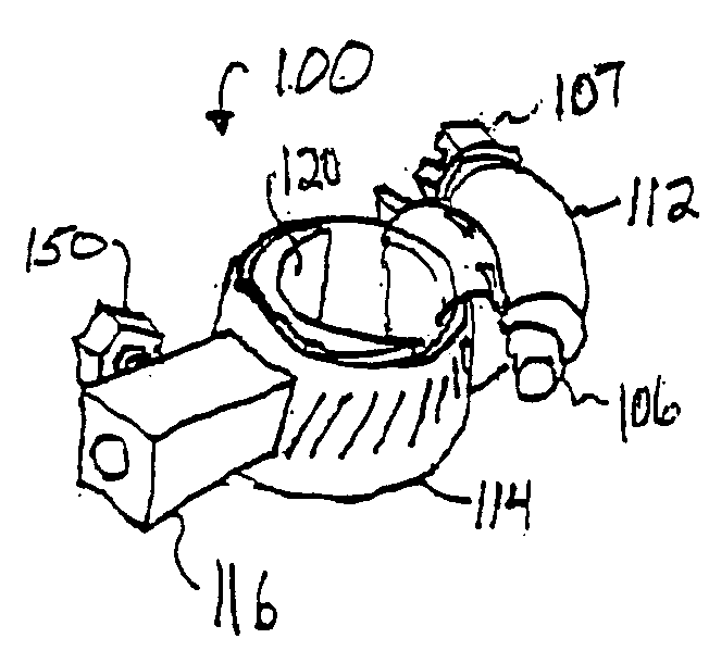
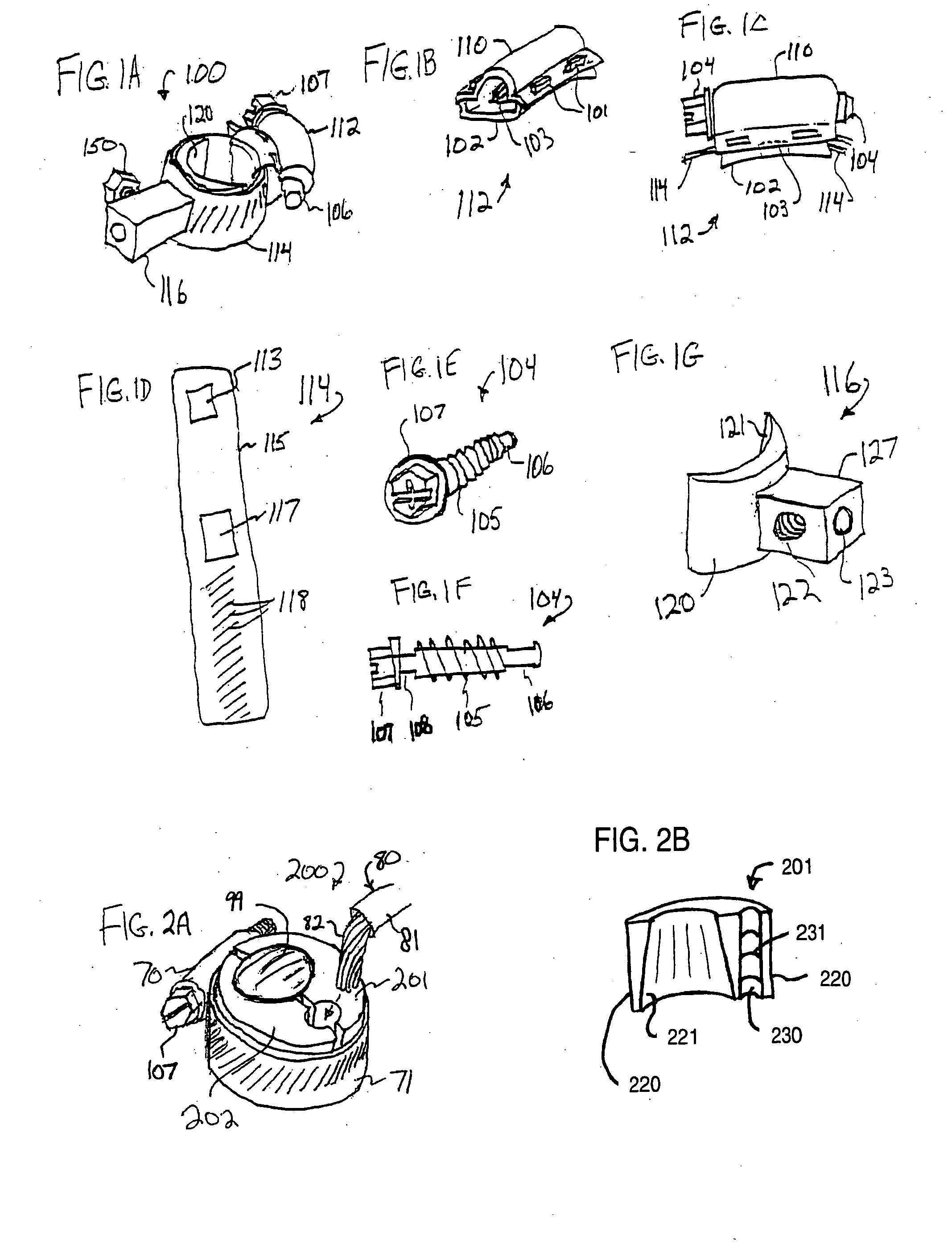
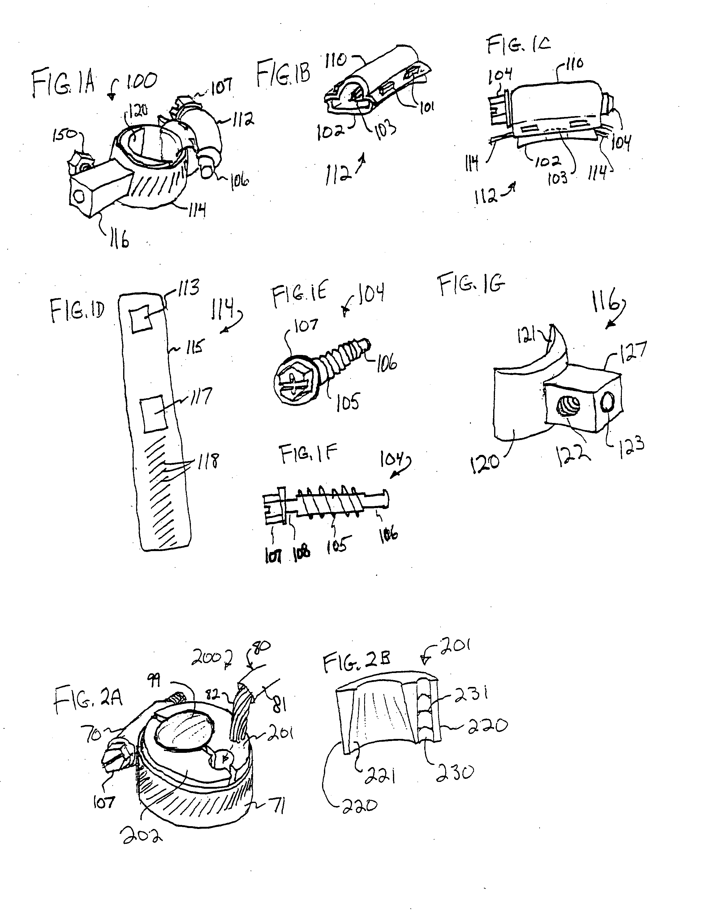
[0060]FIG. 1A is a perspective view that illustrates connector assembly 100 of some embodiments, including a worm drive adjustment assembl...


PUM


Abstract

An electromechanical connector for use between a power source such as a battery and a device requiring the power such as an automotive electrical system. In some embodiments, the connector includes a radius electrical contact constituting a primary electrical current path, and a band clamp with a slotted band constituting a secondary current path, and a worm drive adjustment assembly for symmetrically tighten the connector to the battery post. A kit is described having an electrical-contact conductor with a concave surface conforming to a battery post, and a band clamp to symmetrically compress the conductor against the post. Some embodiments provide a conductor that conforms to an outer portion of the post, and includes a band clamp mechanism with a band fixed at a non-moving end to the conductor, and at an opposite slotted end interfacing to a worm screw held against the conductor.

Description

RELATED APPLICATION [0001] This claims priority to U.S. Provisional Patent Application 60 / 505,475 with filing date Sep. 25, 2003, which is incorporated in its entirety by reference.FIELD OF THE INVENTION [0002] This invention relates generally to battery power systems and more specifically to symmetrically adjustable corrosion-resistant battery cable connectors and connection methods for automotive and marine battery power systems. BACKGROUND OF THE INVENTION [0003] Batteries typically are connected to their loads using a wire of suitable gauge terminated with a connector that is removably connectable to a battery terminal. Some conventional battery-post connectors provide a split-ring connector made of lead metal, having a tapered cylindrical primary opening, connected at a closed end to a cable wire, and having a steel nut-and-bolt fastener that passes through the open end and draws the two edges of the open end together when tightened, in order to provide a tight connection aroun...

Claims


Application Information

Patent Timeline
IPC IPC(8): H01R11/28
CPCH01R11/285Y10T24/1441Y10T24/1427
Inventor MAXWELL, SCOTT D.DRAGGIE, RAYMOND Q.MAXWELL, MARIANLEMAIRE, CHARLES A.
Owner MECHANICAL ANSWERS
Why Eureka
Try Eureka