Apparatus and method of heartbeat mechanism using remote mirroring link for multiple storage system

a heartbeat mechanism and remote mirroring technology, applied in the field of storage systems, can solve the problems of data loss if the primary system is not efficient, the storage system cannot efficiently execute write requests from the host, and the primary system cannot be placed too far apart, and achieve the effect of greater reliability

Inactive Publication Date: 2005-05-19
HITACHI LTD
View PDF15 Cites 36 Cited by
  • Summary
  • Abstract
  • Description
  • Claims
  • Application Information

AI Technical Summary

Benefits of technology

[0008] Embodiments of the present invention provide one or more of the following features: (1) enable discovery of the remotely linked storage system via remote mirroring links, (2) share information on remotely linked storage systems among storage systems in the same cluster, (3) monitor the vitality of directly-linked remote storage systems, (4) obtain vitality of indirectly-linked remote storage syst...

Problems solved by technology

However, the primary and secondary storage systems cannot be placed too far apart, e.g., over 100 miles, under this mode.
Otherwise, the storage system may not efficiently execute write requests from the host.
However, data may be lost if the ...

Method used


Image

  • Apparatus and method of heartbeat mechanism using remote mirroring link for multiple storage system
  • Apparatus and method of heartbeat mechanism using remote mirroring link for multiple storage system
  • Apparatus and method of heartbeat mechanism using remote mirroring link for multiple storage system

Examples


Embodiment Construction

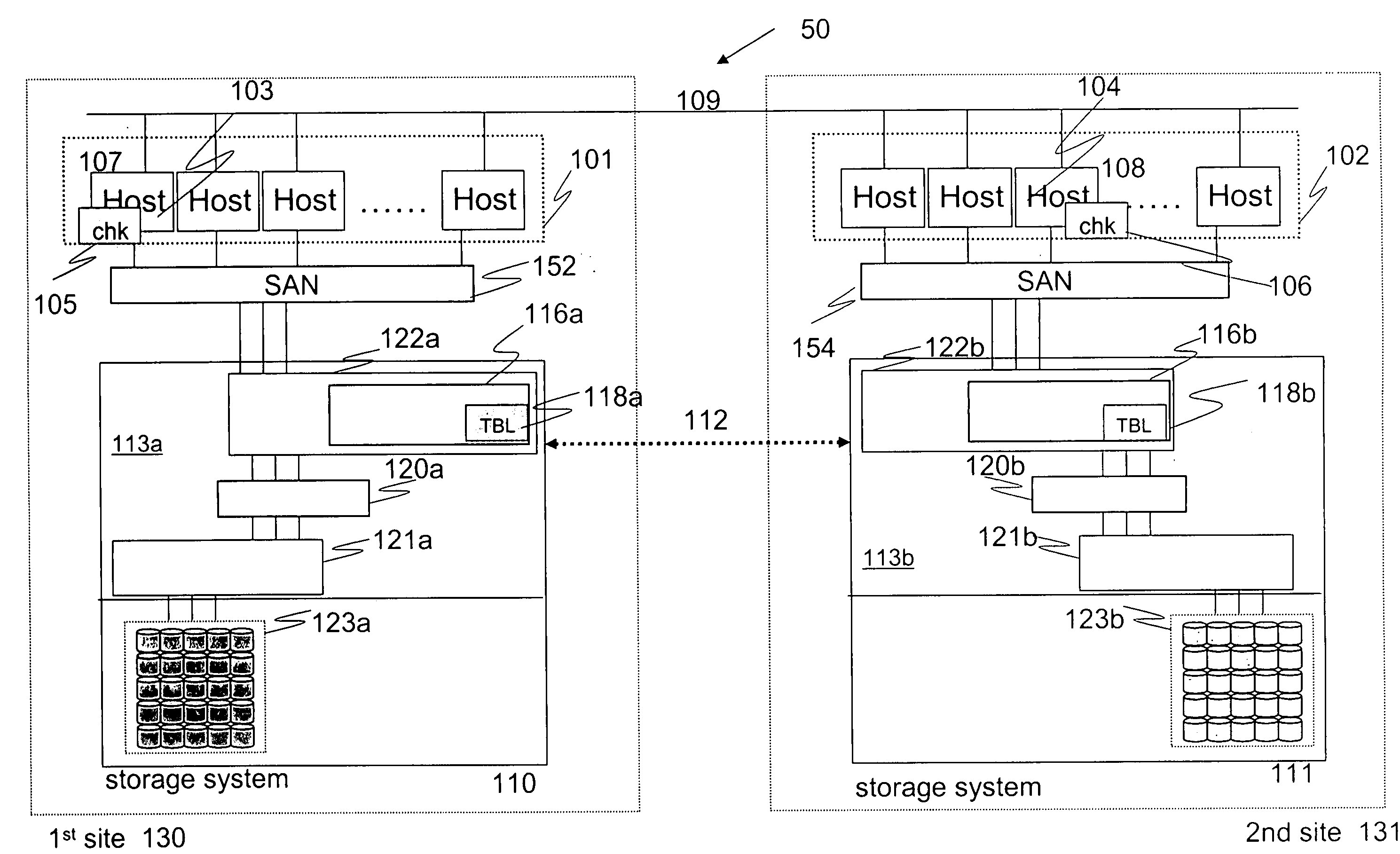
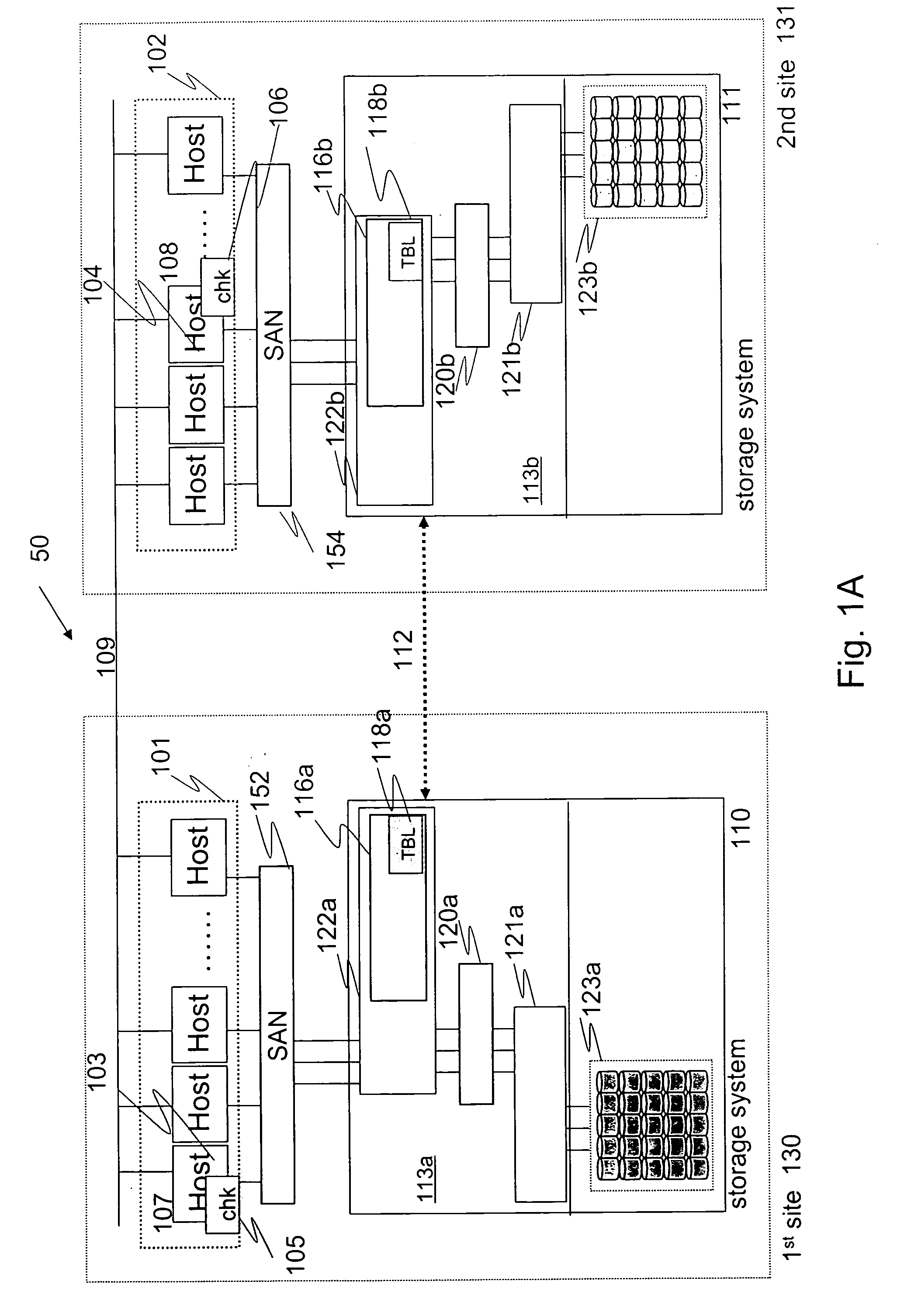
[0035]FIG. 1A illustrates a distributed storage system 50 including a first data site or center 130 and a second data site or center 131. The first site and devices associated with it are also referred to as the primary site and devices, and the second site and devices associated with it are also referred to as the secondary site and devices. The first data center includes a plurality of primary hosts 101 that are configured to send data requests to a storage subsystem 110. The data requests include read and write requests and may be referred to as I / O requests. The storage subsystem 110 includes one or more disk array units. The hosts and storage subsystem are coupled to each other via a communication network, e.g., SAN 152.

[0036] The second data center includes a plurality of secondary hosts 102 that are configured to send data requests (I / O requests) to a storage subsystem 110. The storage subsystem 110 includes one or more disk array units 113a. The hosts and storage subsystem ...


PUM


Abstract

A distributed storage system includes a first data center including a first host and a first storage subsystem that are coupled to each other via a network. The first host includes a first check module configured to handle a heartbeat signal of first type. The first storage subsystem includes a first storage controller and a first monitoring module. The first monitoring module is configured to handle a heartbeat signal of second type. A second data center includes a second host and a second storage subsystem that are coupled to each other via a network. The second host includes a second check module configured to handle the heartbeat signal of first type. The second storage subsystem includes a second storage controller and a second monitoring module. The second monitoring module is configured to handle the heartbeat signal of second type. A third data center includes a third storage subsystem that are coupled to each other via a network. The third host includes a third check module configured to handle the heartbeat signal of first type. The third storage subsystem including a third storage controller and a third monitoring module. The third monitoring module is configured to handle the heartbeat signal of second type. A first communication network couples the first and second third hosts, wherein the hosts use the first communication network to transmit or receive the heartbeat signal of first type. A second communication network couples the first, second, and third storage subsystems, wherein the subsystems use the second communication network to transmit or receive the heartbeat signal of second type.

Description

BACKGROUND OF THE INVENTION [0001] The present invention relates to a storage system, more particularly, to a storage system distributed in multiple sites. [0002] Data is the underlying resources on which all computing processes are based. With the recent explosive growth of the Internet and e-business, the demand on data storage systems has increased tremendously. Types of storage systems include a network-attached storage (NAS) or storage area network (SAN). A NAS uses IP over Ethernet to transports data in file formats between storage servers and their clients. In NAS, an integrated storage system, such as a disk array or tape device, connects directly to a messaging network through a local area network (LAN) interface, such as Ethernet, using messaging communications protocols like TCP / IP. The storage system functions as a server in a client-server system. [0003] Generally, a SAN is a dedicated high performance network to move data between heterogeneous servers and storage resou...

Claims


Application Information

Patent Timeline
IPC IPC(8): G06F7/00H04L12/24H04L12/26
CPCH04L43/10
Inventor FUJIBAYASHI, AKIRA
Owner HITACHI LTD
Why Eureka
Try Eureka