Storage device and controlling method thereof

a storage device and control method technology, applied in the direction of instruments, input/output to record carriers, computing, etc., can solve the problems of difficult to apply the prior art to a disk device, difficult to raise the back-end throughput, and high cost of a disk device having a considerable number of disk drives equipped with high-speed interfaces

Inactive Publication Date: 2005-05-19
HITACHI LTD
View PDF9 Cites 41 Cited by
  • Summary
  • Abstract
  • Description
  • Claims
  • Application Information

AI Technical Summary

Benefits of technology

[0013] It is another object of the present invention to provide a disk device having a high-reliability back-end network.

Problems solved by technology

First, because a disk drive contains mechanical parts, the throughput in the back-end is harder to raise than in the front-end where only electronic and optical elements are to be improved to raise the throughput.
Second, even if a disk drive is enhanced to operate at a sufficiently high rate, a disk device having a considerable number of disk drives which are all equipped with high-speed interfaces will be high cost.
The Prior Art 1 does not take a disk drive having a plurality of I / O ports into consideration and it is difficult to apply the Prior Art 1 to a disk device comprising disk drives each having a plurality of I / O ports in the back-end.
In the Prior Art 2, dynamic control is required when data is transferred and its problem is complexity of the control method.

Method used


Image

  • Storage device and controlling method thereof
  • Storage device and controlling method thereof
  • Storage device and controlling method thereof

Examples


embodiment 1

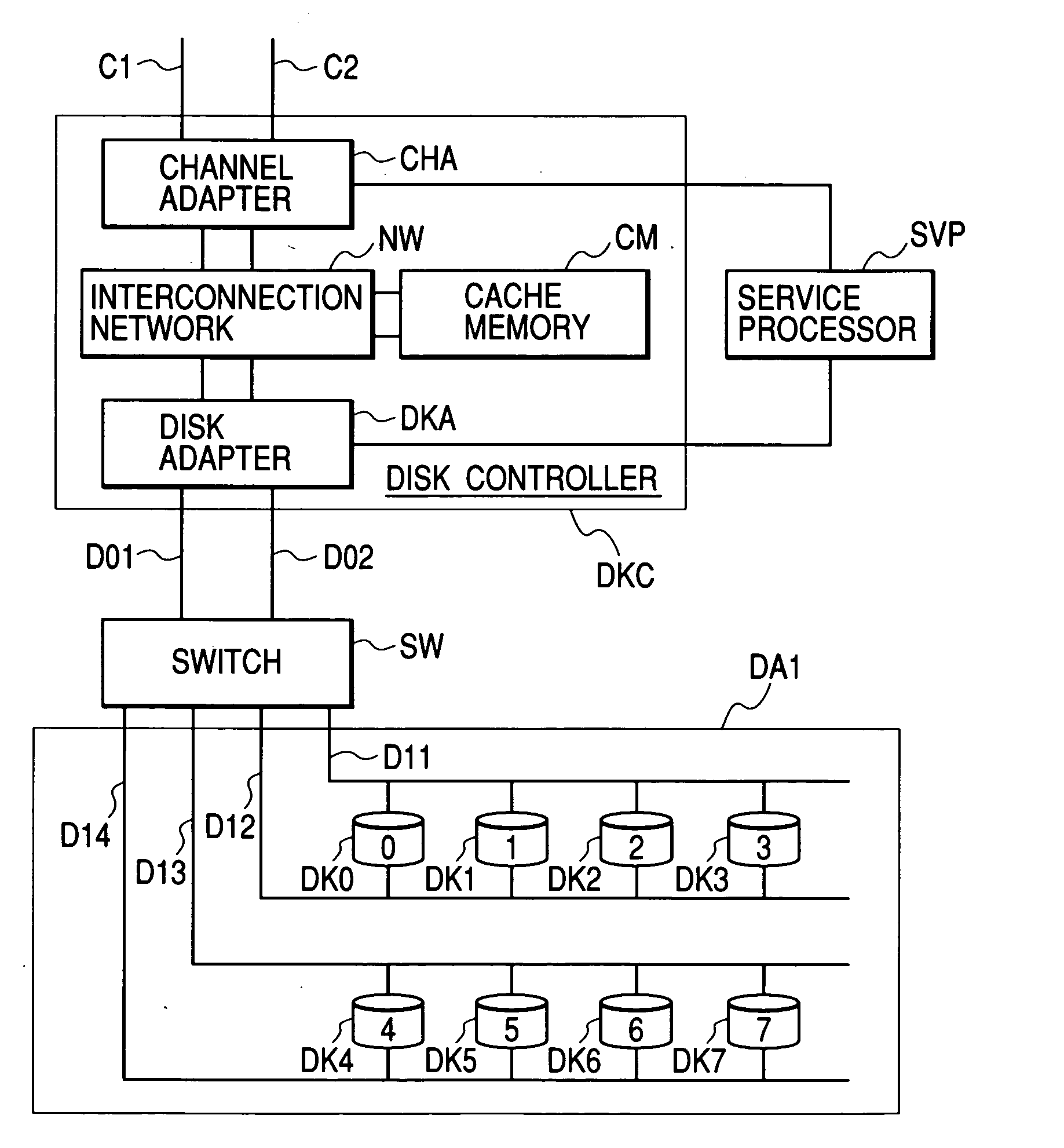
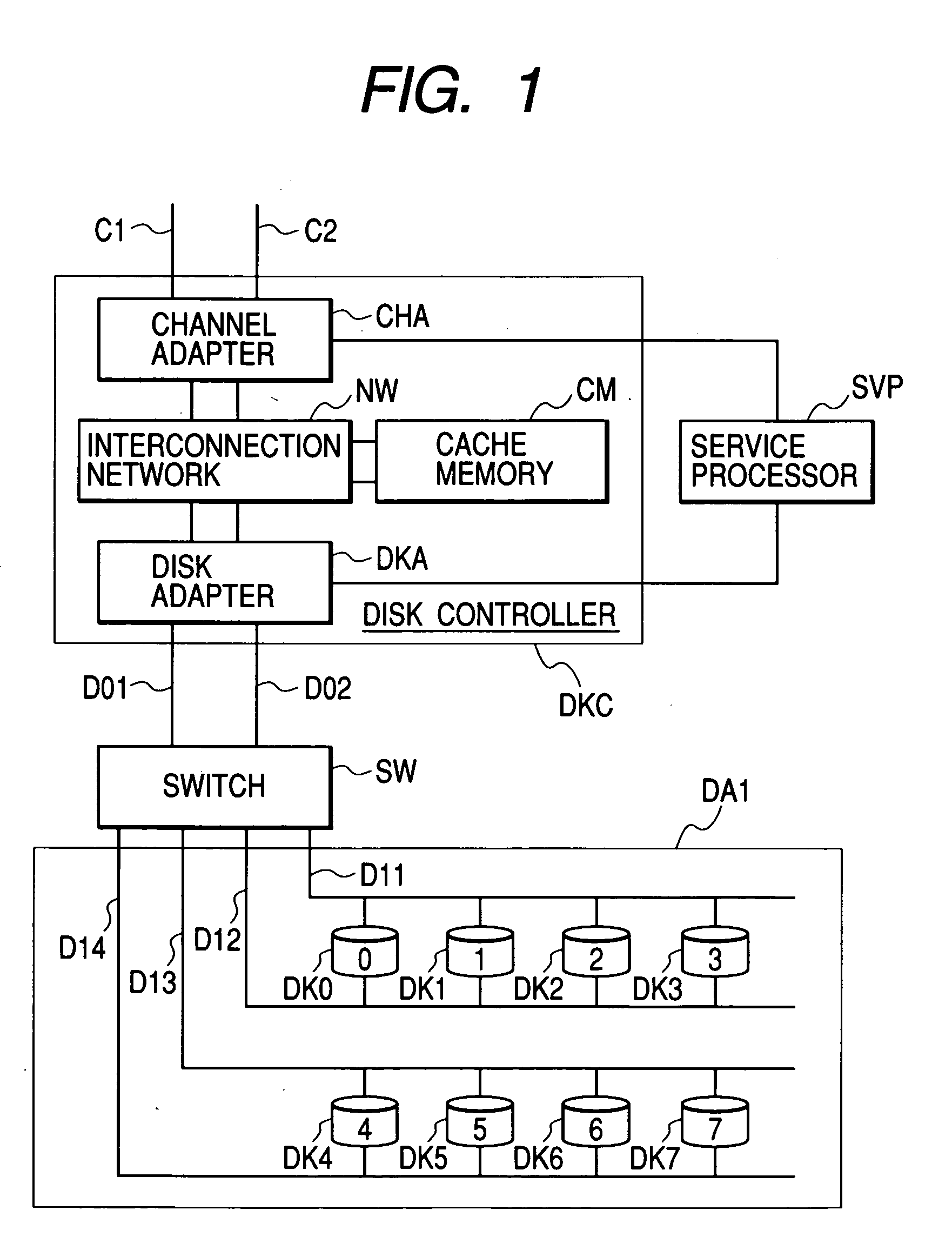
[0051]FIG. 1 shows a disk device configuration according to a preferred Embodiment 1 of the invention. The disk device is comprised of a disk controller (DKC), a disk array (DA1), and a switch (SW). The disk controller (DKC) is comprised of a channel adapter (CHA), a cache memory (CM), and a disk adapter (DKA). The channel adapter (CHA), the cache memory (CM), and the disk adapter (DKA) are connected by an interconnection network (NW). The channel adapter (CHA) connects to a host system (not shown) through channels (C1) and (C2). The disk adapter (DKA) is connected to the disk array (DA1) through channels (D01) and (D02) and via the switch (SW).

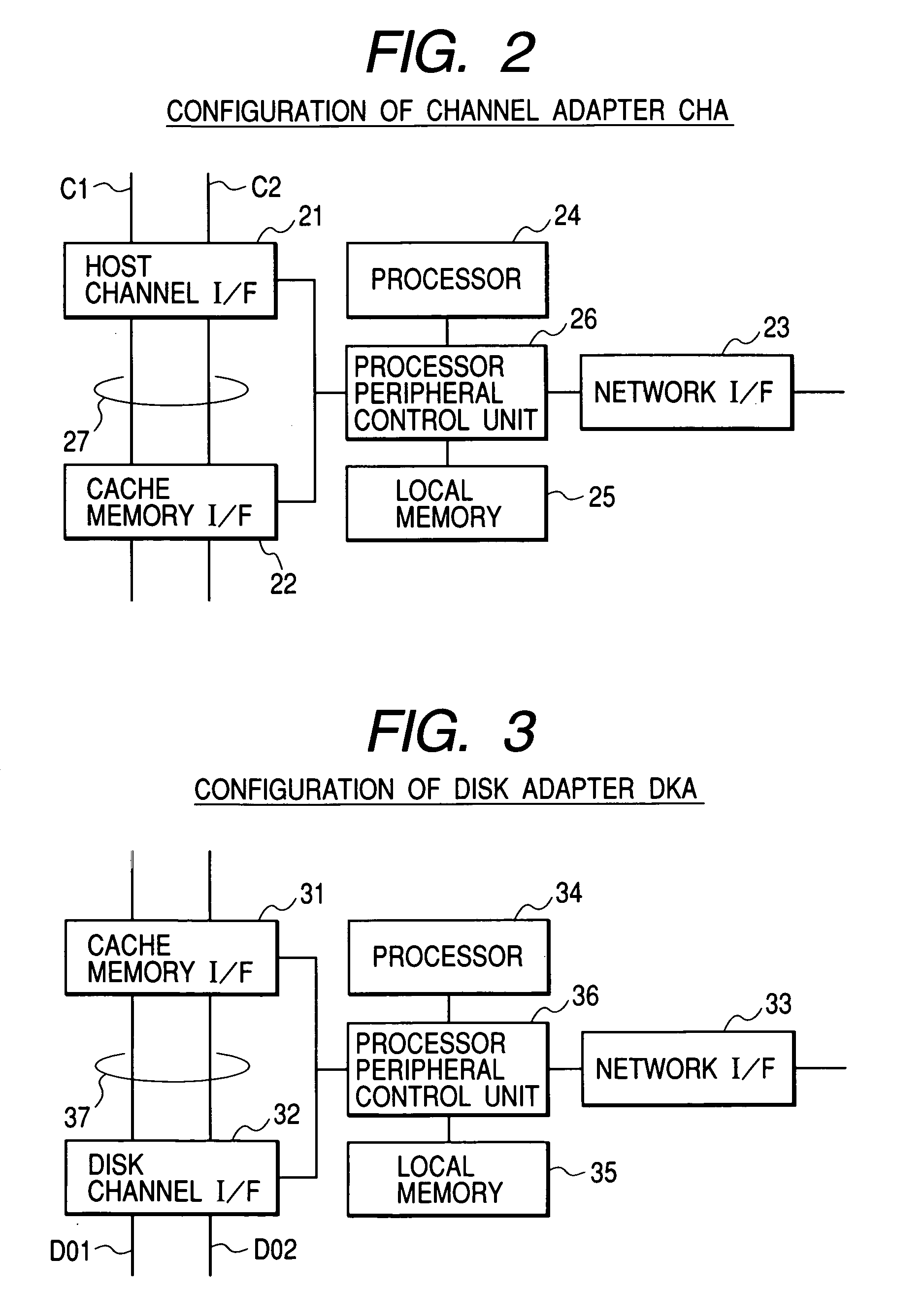
[0052]FIG. 2 shows a configuration of the channel adapter.

[0053] The channel adapter is comprised of a host channel interface 21 on which the channels C1 and C2 terminated, a cache memory interface 22 connected to the interconnection network, a network interface 23 for making connection to a service processor, a processor 24 for controlling...

embodiment 2

[0071]FIG. 8 through FIGS. 11A and 11B are provided to explain a preferred Embodiment 2. In Embodiment 2, the switch modifies information within a frame so that full duplex operation is implemented, irrespective of the destination drive port set by the disk adapter.

[0072]FIG. 8 shows a switch configuration used in Embodiment 2. To the switch configuration of FIG. 5, a memory 812 is added, and a switch unit 810 is a shared memory type. A processor 811 is able to read data from and write data to frames stored on the shared memory switch 810. On the memory 812, management tables which are shown in FIGS. 11A and 11B are stored. The processor 811 executes frame modification processing, according to a flowchart of FIG. 10. In the management table of FIG. 11A, a destination port ID 1101 within a frame sent from the disk adapter to the switch is mapped to alternate port IDs 1102 and 1103. A column 1102 contains alternate port IDs for Read exchanges and a column 1103 contains alternate port...

embodiment 3

[0080]FIG. 12 shows a disk device configuration example according to a preferred Embodiment 3 of the invention. A feature of the disk device of Embodiment 3 lies in duplicated switches. In Embodiment 3, Fiber Channel is used for data transfer between a disk adapter and switches SW1 and SW2 and data transfer between the switches SW1 and SW2 and a disk array DA2.

[0081] The disk device of Embodiment 3 is comprised of a disk controller (DKC), the switches SW1 and SW2, and the disk array DA2. The disk controller is comprised of a channel adapter (CHA), a cache memory (CM), and a disk adapter (DKA).

[0082] The disk adapter and the switch SW1 are connected by a channel D01 and the disk adapter and the switch SW2 are connected by a channel D02. The switch SW1 and the switch SW2 are connected by a channel 1201.

[0083] Disk drives constituting the disk array DA2 each have two I / O ports. For example, disk drives DK0, DK4, DK8, and DK12 connect to both channels D11 and D21. The disk array DA2 ...


PUM


Abstract

A disk adapter and disk drives, each having dual ports, are connected in dual loops via a switch. A destination loop to which a command is to be transferred is determined, according to the type (Read/Write) of the command that the disk adapter issues to one of the disk drives. The disk adapter issues Read and Write commands so that the Read exchange and the Write exchange are executed in parallel.

Description

BACKGROUND OF THE INVENTION [0001] In current computer systems, data required by a CPU (Central Processing Unit) is stored in secondary storage devices and writing data to and reading data from the secondary storage devices are performed when necessary for the CPU and related operation. As these secondary storage devices, nonvolatile storage media are generally used, typified by disk devices comprising magnetic disk drives, optical disk drives, and the like. With advancement of information technology in recent years, there is a demand for higher performance of these secondary storage devices in the computer systems. [0002] As I / O interfaces of high performance disk devices, Fibre Channel is often used. Connection topologies of the Fiber Channel are shown in FIGS. 20, 21, and 22. FIG. 20 shows a “point to point” topology. In this topology, Fibre Channel ports are called N_Ports and interconnection between a pair of N_Ports is made by two physical channels through which data is transm...

Claims


Application Information

Patent Timeline
Patent Type & Authority Applications(United States)
IPC IPC(8): G06F3/06G06F13/12G06F12/00
CPCG06F3/0613G06F3/0658H04L67/1097G06F3/0689G06F12/0866G06F3/0659
Inventor TANAKA, KATSUYASHIROGANE, TETSUYA
Owner HITACHI LTD
Why Eureka
Try Eureka