Laser cathode ray tube

Inactive Publication Date: 2005-05-26
PRINCIPIA LIGHTWORKS
View PDF24 Cites 17 Cited by
  • Summary
  • Abstract
  • Description
  • Claims
  • Application Information

AI Technical Summary

Benefits of technology

[0011] In one embodiment, a Laser-CRT is described in which the laser faceplate is at high potential, the cathode is above ground, the G1 electrode is below ground, and the cathode is modulated along with the G1 electrode in a dua

Problems solved by technology

However, conventional projection CRTs have significant technical restrictions that limit their effectiveness.
Although the amount of light produced by conventional CRTs may be somewhat acceptable for images projected over short distances and expanded to small areas (i.e., less than a few square feet), the projected image becomes increasingly dim and eventually becomes unacceptable when projected over increasingly longer distances and spread over larger areas.
Furthermore, phosphors simply cannot produce high luminous flux, lack of which causes a dimly-contrasted projected image, whose limitations become especially apparent over longer projection distances and greater area expansions.
Because the laser faceplate is usually connected to a glass tube by a metallic ring and is in direct contact with the cooling fluid, the application of high voltage to the laser faceplate in this c

Method used


Image

  • Laser cathode ray tube
  • Laser cathode ray tube
  • Laser cathode ray tube

Examples


Embodiment Construction

[0022] This invention is described in the following description with reference to the Figures, in which like numbers represent the same or similar elements.

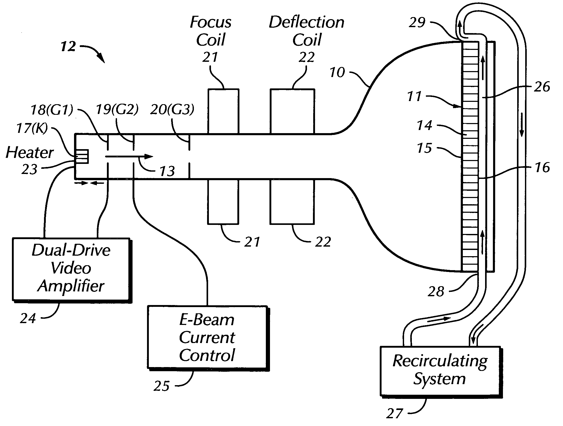
[0023] A Laser-CRT described herein includes a vacuum tube that has a laser faceplate that emits laser radiation in response to impingement by an electron beam.

[0024]FIG. 1 is a cross-sectional view of a Laser-CRT that includes a funnel-shaped glass envelope 10 that forms the outer surface of a vacuum tube. A laser faceplate 11 is situated on the wide end of the funnel, and the narrow opposite end includes an electron gun apparatus 12 that generates and directs the electron beam 13 to the faceplate. In one embodiment the laser faceplate includes a layer of active gain material 14 situated between two reflective layers (including one fully reflective layer 15 and one partially reflective layer 16) to define a laser cavity area. Since the laser area is typically homogeneous across the faceplate, laser action is created at the poi...


PUM


Abstract

A Laser-CRT is described in which the laser faceplate is at high potential and the cathode is above ground. The cathodes can be modulated in a dual-drive or push-pull mode in which each of the dual video amplifiers is required to swing only half of the total required voltage, thereby writing smaller pixels faster and achieving higher resolution. Another described embodiment provides a substantially constant laser output over time, and an approximately uniform output intensity over an area. A constant-output Laser-CRT can be used to illuminate a spatial light modulator (SLM) in a projection system, and since video modulation is not required in that embodiment, neither are costly electronics and merely a voltage bias need be applied to the electron gun (e.g., the K electrode) to turn on the electron beam.

Description

CROSS-REFERENCE TO RELATED APPLICATION [0001] Priority is hereby claimed to U.S. Provisional Patent Application No. 60 / 516,771, filed Nov. 3, 2003, entitled LASER CATHODE RAY TUBE, which is incorporated by reference herein in its entirety.BACKGROUND [0002] 1. Field of the Invention [0003] This invention relates to electronic devices, and more particularly to laser cathode ray tubes such as those used in projection televisions or as coherent light sources. [0004] 2. Description of Related Art [0005] Conventional cathode ray tubes (CRTs) use phosphors to produce light responsive to an electron beam scanned on the screen containing the phosphors. A conventional CRT includes a funnel-shaped vacuum tube that has a phosphor screen on its wide end. On its narrow end, a conventional CRT has an electron gun including a cathode for generating electrons, a magnetic coil to focus the electrons into a beam, and a deflection coil to deflect and scan the electron beam. In operation, the phosphors ...

Claims


Application Information

Patent Timeline
IPC IPC(8): H01J29/89H01J31/10
CPCH01J29/89H01J2229/8928H01J2229/0084H01J31/10
Inventor TIBERI, MICHAEL D.VANCIL, BERNARD K.
Owner PRINCIPIA LIGHTWORKS
Why Eureka
Try Eureka