Plasma display panel

a technology of display panel and plasma, which is applied in the direction of static indicating devices, instruments, and address electrodes, etc., can solve the problems of limiting the size of the discharge distance within a small discharge area of a pdp, affecting the efficiency of the fluorescent layer, etc., to achieve efficient conversion of ultraviolet rays and high luminance

Inactive Publication Date: 2005-05-26
SAMSUNG SDI CO LTD
View PDF4 Cites 14 Cited by
  • Summary
  • Abstract
  • Description
  • Claims
  • Application Information

AI Technical Summary

Benefits of technology

[0009] It is also an object to provide a design for a plasma display panel that improves on the luminance efficiency.
[0011] These and other objects can be achieved by a PDP that more efficiently converts ultraviolet rays generated from a plasma into visible images of high luminance. According to an aspect of the present invention, there is provided a PDP that includes a container having a gas discharge area and a discharge generating unit generating a discharge in the discharge area, the discharge area includes a first fluorescent layer converting both ultraviolet rays and shorter wavelength vacuum ultraviolet rays (VUV) into visible rays, and a second fluorescent layer converting VUV rays into longer wavelength ultraviolet rays.

Problems solved by technology

However, there is a limit as to the size of the discharge distance within a small discharge area of a PDP.
However, a significant amount of the generated ultraviolet rays never reach and activate the fluorescent material leading to waste.
The ultraviolet rays produced in discharge area 8 are radiated in every direction and thus some rays never reach the fluorescent layer, producing wasted energy.
However, the fluorescent layer 7 may not be able to convert the VUV rays into visible light, further producing waste.

Method used


Image

  • Plasma display panel
  • Plasma display panel
  • Plasma display panel

Examples


Embodiment Construction

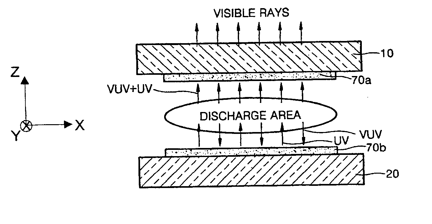
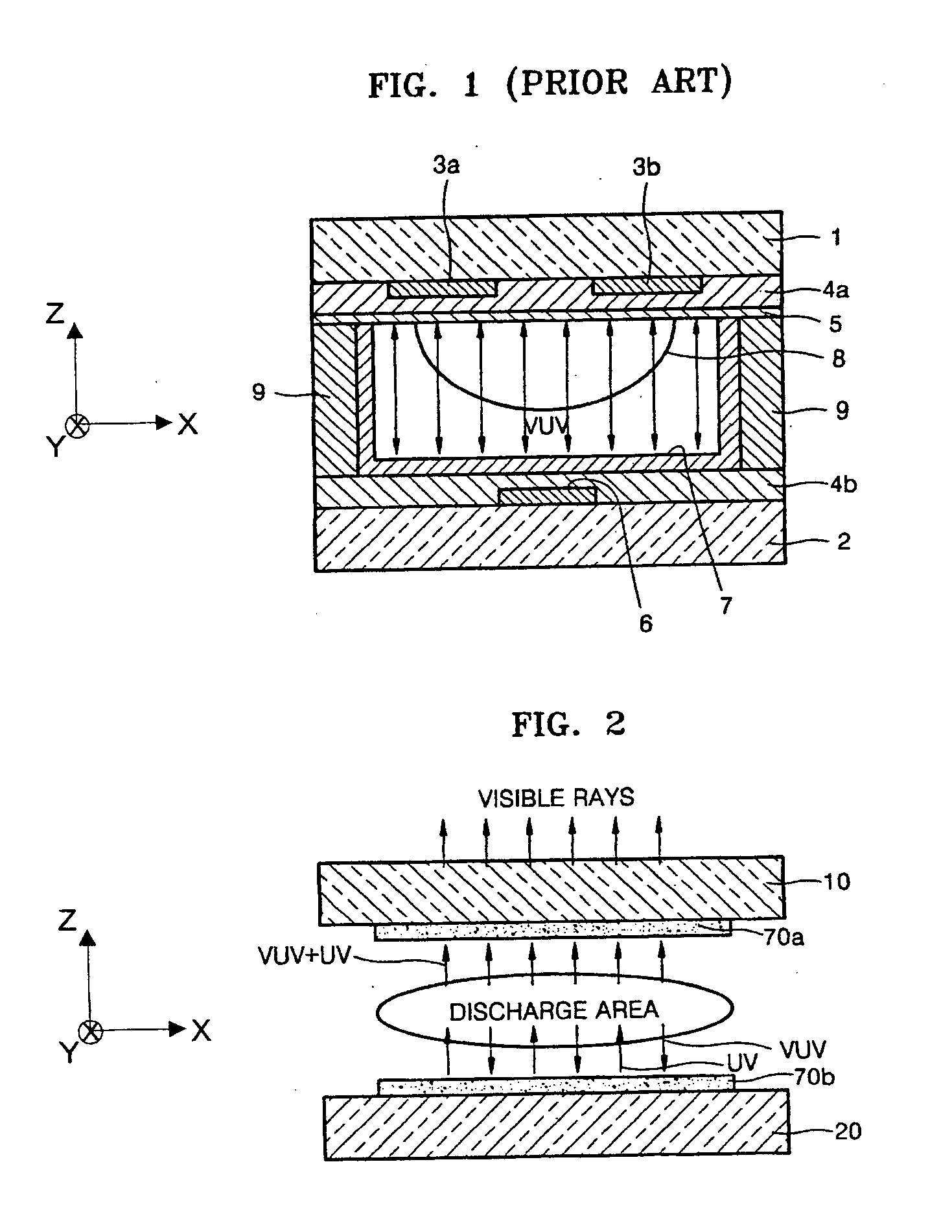
[0020] Turning now to FIG. 2, FIG. 2 is a sectional view for explaining a method of generating visible rays by using ultraviolet rays including vacuum ultraviolet rays (VUV) that are generated in a discharge area according to the present invention. Referring to FIG. 2, a front plate 10 and a rear plate 20 are arranged at both sides of a gas plasma discharge area, and a first fluorescent layer 70a is formed on the surface of the front plate 10 facing the rear plate 20 and a second fluorescent layer 70b is formed on the surface of the rear plate 20 facing the front plate 10.

[0021] The first fluorescent layer 70a is formed of a fluorescent material is able to convert both the ultraviolet rays and the shorter wavelength VUV rays into visible light. The second fluorescent layer 70b is formed of a fluorescent material that converts VUV into ultraviolet rays having a longer wavelength than VUV. The ultraviolet rays and the VUV generated in the discharge area progress in every direction, a...


PUM


Abstract

A design for a plasma display panel (PDP). The novel PDP has two separate layers of fluorescent material. One layer of fluorescent material can generate long wavelength from VUV rays and the other fluorescent layer can convert either of VUV or long wavelength ultraviolet rays into visible rays. Such a PDP improves the luminance efficiency by more efficiently using the UV and VUV rays generated during plasma discharge.

Description

CLAIM OF PRIORITY [0001] This application makes reference to, incorporates the same herein, and claims all benefits accruing under 35 U.S.C. § 119 from an application for PLASMA DISPLAY PANEL earlier filed in the Korean Intellectual Property Office on 24 Nov. 2003 and there duly assigned Serial No. 2003-83617. BACKGROUND OF THE INVENTION [0002] 1. Field of the Invention [0003] The present invention relates to a plasma display panel (PDP), and more particularly, to a design for a PDP resulting in improved luminous efficiency. [0004] 2. Description of the Related Art [0005] A PDP generates visible rays of a predetermined wavelength from a fluorescent material energized by ultraviolet rays in a plasma discharge. The amount of visible rays depends on a discharge distance. However, there is a limit as to the size of the discharge distance within a small discharge area of a PDP. In order to display images of high luminance, a large amount of ultraviolet rays are required and it is necessa...

Claims


Application Information

Patent Timeline
Patent Type & Authority Applications(United States)
IPC IPC(8): H01J11/12H01J11/14H01J11/16H01J11/22H01J11/24H01J11/26H01J11/32H01J11/34H01J11/36H01J11/42
CPCH01J11/42H01J11/16H01J11/24H01J11/26
Inventor ZENG, XIAOQINGHATANAKA, HIDEKAZUKIM, YOUNG-MOLEE, SEONG-EUIJANG, SANG-HUNSON, SEUNG-HYUNGKIM, GI-YONGPARK, HYOUNG-BIN
Owner SAMSUNG SDI CO LTD
Why Eureka
Try Eureka