Additional fringe field shield for a superconducting magnet coil system

Active Publication Date: 2005-05-26
HITACHI GLOBAL STORAGE TECH JAPAN LTD +1
View PDF16 Cites 7 Cited by
  • Summary
  • Abstract
  • Description
  • Claims
  • Application Information

AI Technical Summary

Benefits of technology

[0014] In an alternative embodiment, the radially inner shielding cylinder and/or the further radially outer shielding cylinder are designed as resistive shielding cylinder(s), in particular, made from Cu or Al. Cu or Al are thereby typically present in the form of flat sheet metal. Purchase and maintenance of this embodiment are particularly inexpensive.
[0015] In another preferred embodiment, the further radially outer shielding cylinder is wound from wire, in particular, superconducting wire, and

Problems solved by technology

In consequence thereof, the fringe field outside of the radially outer shiel

Method used


Image

  • Additional fringe field shield for a superconducting magnet coil system
  • Additional fringe field shield for a superconducting magnet coil system

Examples


Embodiment Construction

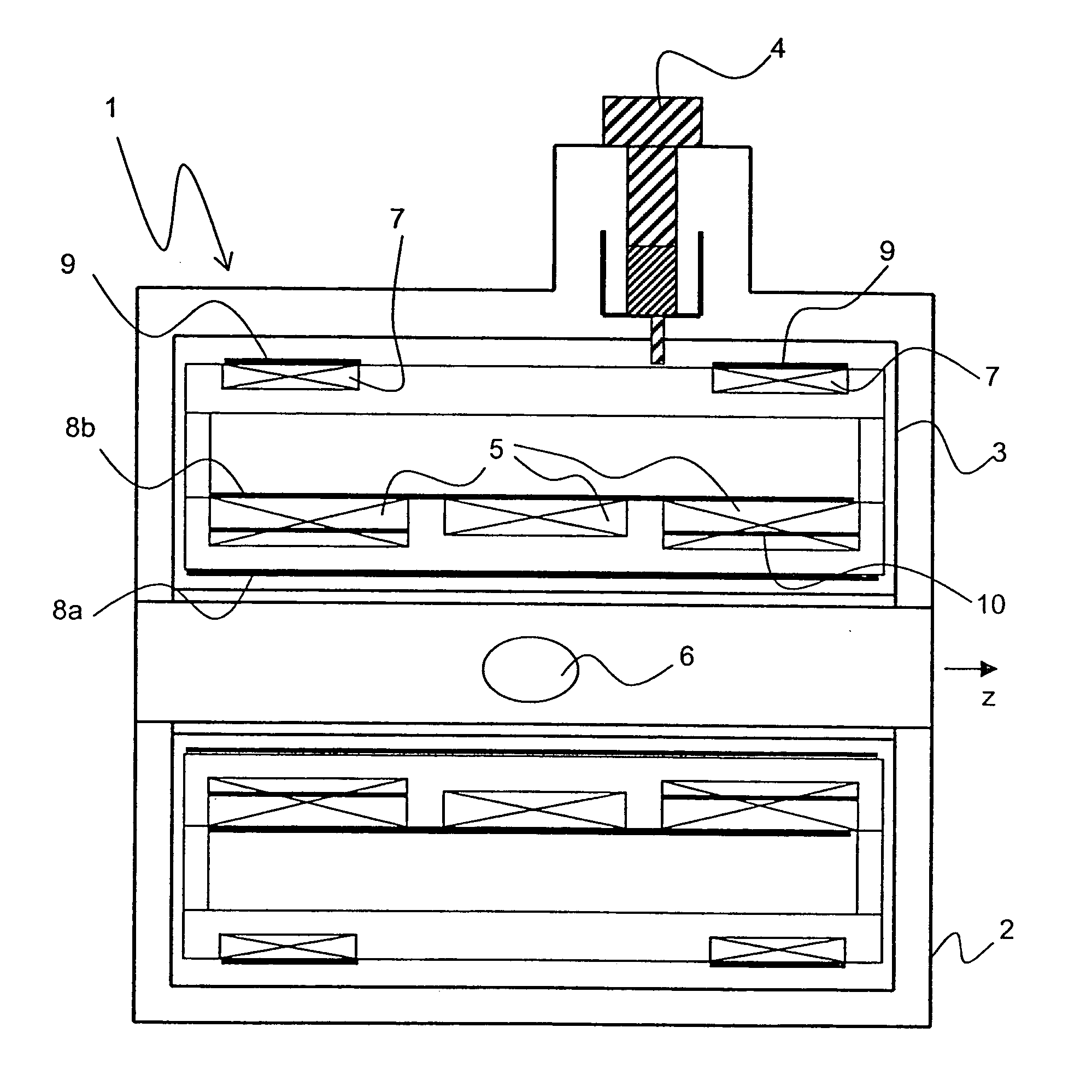
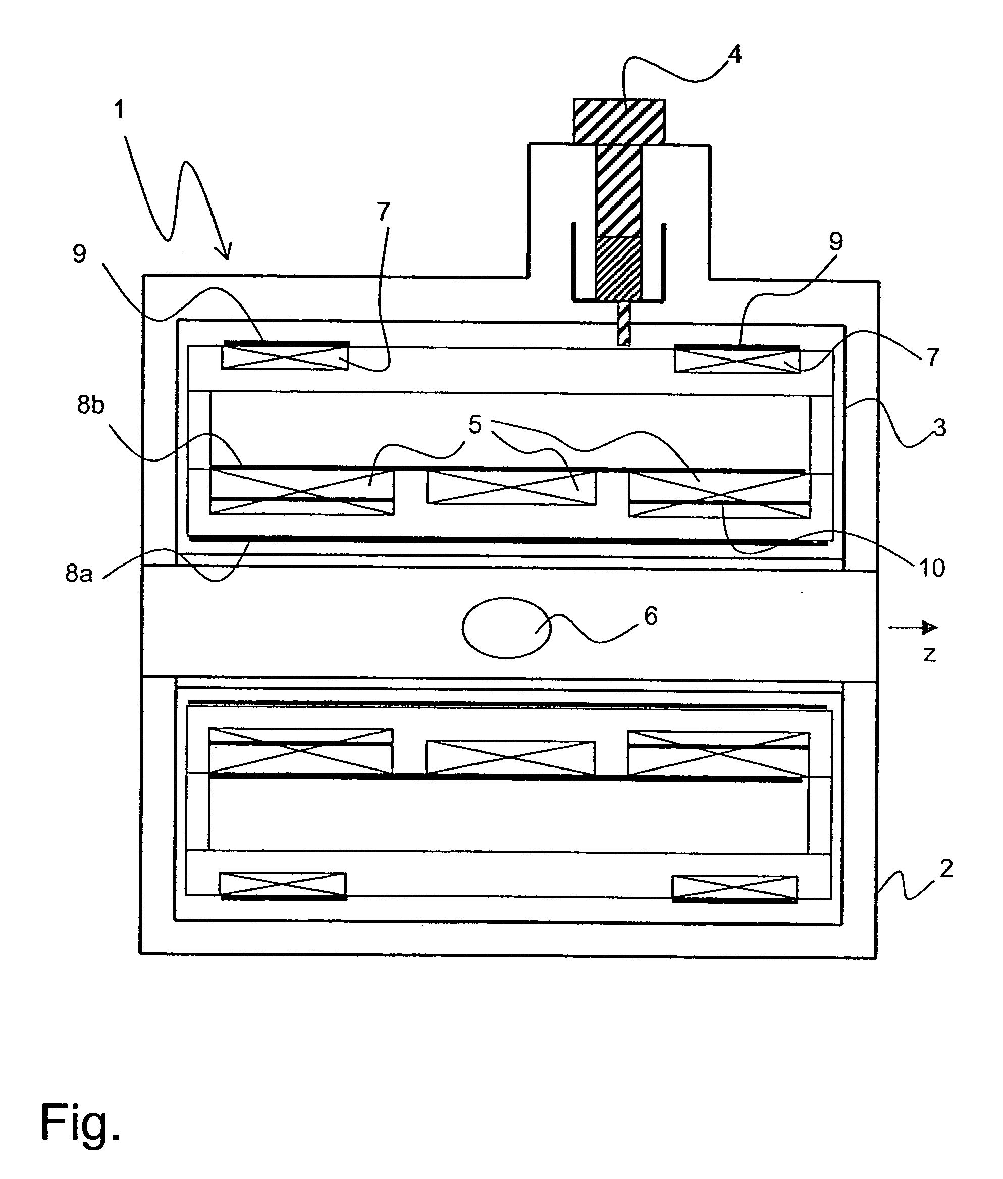
[0020] The inventive magnet coil system 1 in the figure comprises a vacuum tank 2 which contains a helium tank 3 which is approximately half filled with liquid helium. The helium is cooled through a refrigerator comprising a cooling head 4 which projects into the helium tank 3.

[0021] The helium tank 3 has a main field winding 5 which is superconducting during operation. The main field winding 5 generates a strong homogeneous magnetic field at the location of a working volume 6. This magnetic field is rotationally symmetric about a horizontal axis which extends through the working volume 6 and defines a z-direction. To prevent fringe fields outside of the magnet coil system 1, the magnet coil system 1 also comprises a shielding winding 7. It is disposed at a radial separation, outside of the main field winding 5. During normal operation, the current flow in the shielding winding 7 is opposite to the current flow in the main field winding 5.

[0022] The magnet coil system 1 also compr...


PUM


Abstract

An actively shielded superconducting magnet coil system (1) for generating a magnetic field in a working volume (6), which is rotationally symmetric about a z-axis, comprising a radially inner main field winding (5) and a radially outer shielding winding (7), and an electrically highly conductive shielding cylinder (radially inner shielding cylinder) (8a/8b) which is disposed radially inside the main field winding (5) or between main field winding (5) and the shielding winding (7) is characterized in that at least one further electrically highly conductive shielding cylinder (9) is disposed radially outside the shielding winding (7). The inventive magnet coil system prevents generation of a fringe field flash in the outer region of the magnet coil system in case of a quench.

Description

[0001] This application claims Paris Convention priority of DE 103 54 677.4 filed Nov. 22, 2003 the complete disclosure of which is hereby incorporated by reference. BACKGROUND OF THE INVENTION [0002] The invention concerns an actively shielded superconducting magnet coil system for generating a magnetic field in a working volume, which is designed to be rotationally symmetric about a z-axis, comprising a radially inner main field winding and a radially outer shielding winding, and an electrically highly conductive shielding cylinder (radially inner shielding cylinder) which is disposed radially inside the main field winding or between the main field winding and the shielding winding. [0003] An actively shielded magnet coil system without radially inner shielding cylinder is disclosed e.g. in DE 100 33 411 A1. A magnet coil system which is not actively shielded comprising a radially inner shielding cylinder is disclosed e.g. in DE 39 00 725 A1. [0004] Superconducting magnet coil sys...

Claims


Application Information

Patent Timeline
IPC IPC(8): G01R33/3815G01R33/421
CPCG01R33/421G01R33/3815
Inventor WESTPHAL, MICHAEL
Owner HITACHI GLOBAL STORAGE TECH JAPAN LTD
Why Eureka
Try Eureka