Logic circuit apparatus and timeshare operating method of a programmable logic circuit

a logic circuit and operating method technology, applied in the field of logic circuit equipment, can solve problems such as excessive throughput of the entire integrated circui

Inactive Publication Date: 2005-05-26
KK TOSHIBA
View PDF4 Cites 35 Cited by
  • Summary
  • Abstract
  • Description
  • Claims
  • Application Information

AI Technical Summary

Benefits of technology

[0022]FIG. 9 is a flow chart of a unit circuit switching operation by a control unit provided in a logic circuit apparatus of a second embodiment of the present invention;
[0023]FIG. 10 is a flow chart for calculating a priority order of the respective unit circuit by the control u...

Problems solved by technology

However, since some steps only require low throughput, the...

Method used


Image

  • Logic circuit apparatus and timeshare operating method of a programmable logic circuit
  • Logic circuit apparatus and timeshare operating method of a programmable logic circuit
  • Logic circuit apparatus and timeshare operating method of a programmable logic circuit

Examples


first exemplary embodiment

OF A LOGIC CIRCUIT APPARATUS

[0052]FIG. 8 is a block diagram showing a logic circuit apparatus 800 of a first exemplary embodiment of the present invention. This logic circuit apparatus 800 has a programmable logic circuit 801, a circuit arrangement information supplying unit 802, and a circuit arrangement information storage unit 803. The programmable logic circuit 801 is arranged by combining a plurality of the unit blocks 600 with a plurality of unit block-to-block connecting units 610, as shown in FIG. 6. The circuit arrangement information supplying unit 802 supplies circuit arrangement information to the programmable logic circuit 801. The circuit arrangement information storage unit 803 stores circuit arrangement information. This circuit arrangement information is used when the programmable logic circuit 801 constitutes the respective unit circuits.

[0053] The logic circuit apparatus 800 according to this first exemplary embodiment has a FIFO 806, an input FIFO selecting unit...

second exemplary embodiment

OF A LOGIC CIRCUIT APPARATUS

[0088] Next, a description is made of a logic circuit apparatus 800 according to a second exemplary embodiment of the present invention. Since an arrangement of the logic circuit apparatus 800 of this second exemplary embodiment is similar to that of the first embodiment, an explanation thereof is omitted. In this exemplary second embodiment, a selecting process operation (step S902) of a unit circuit, which is executed by the control unit 807, is different from that of the first exemplary embodiment.

[0089] In this second exemplary embodiment, priority degrees of the respective unit circuits are evaluated by four stages defined from a priority degree 1 up to a priority degree 4. The priority degree 1corresponds to the highest priority degree. The priority degree 4 indicates a process impossible status. The control unit 807 of this second exemplary embodiment selects a unit circuit having the highest priority degree.

[0090]FIG. 10 is a flow chart for expl...

third exemplary embodiment

LOGIC CIRCUIT APPARATUS OF A THIRD EXEMPLARY EMBODIMENT

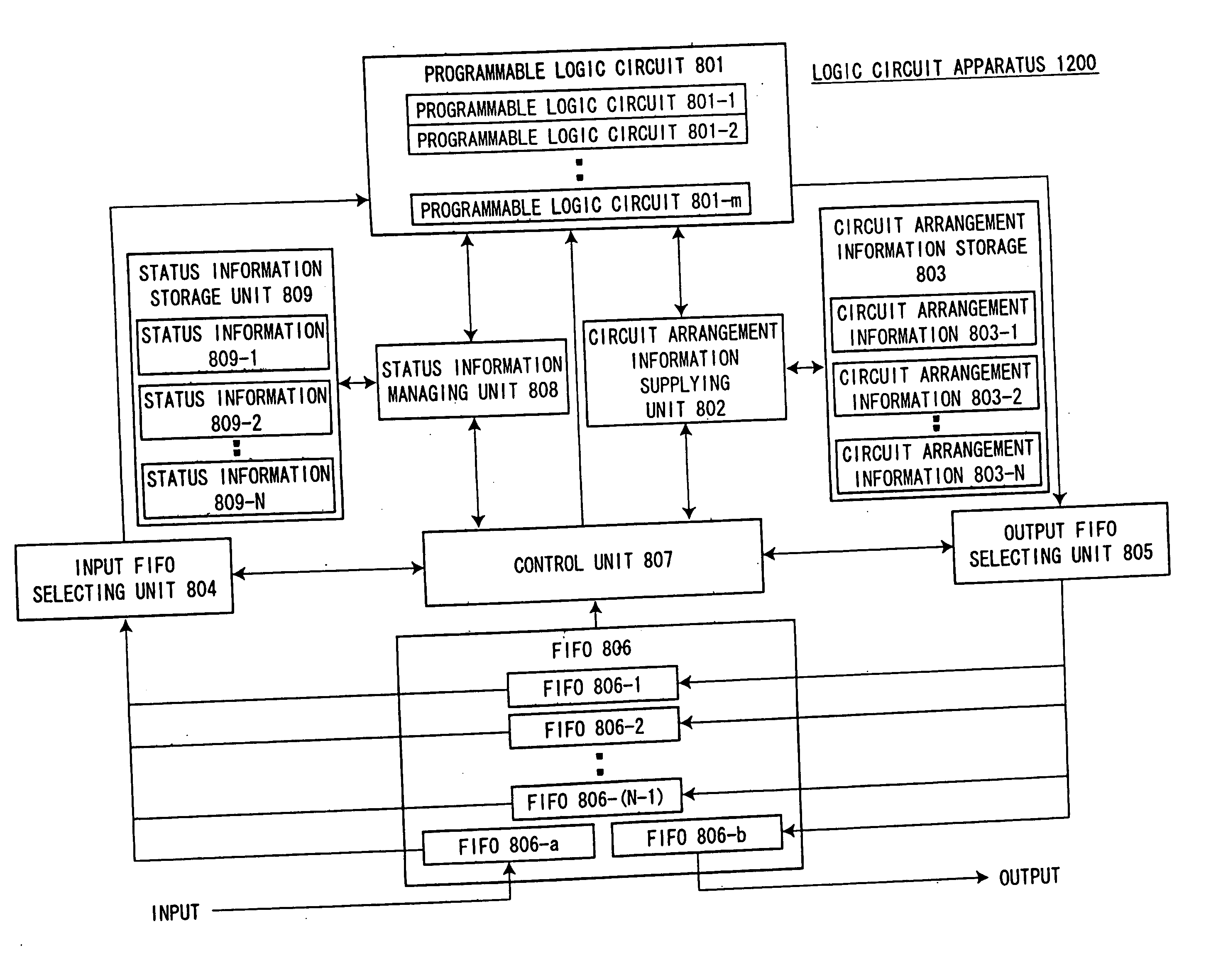
[0106] A logic circuit apparatus according to a third embodiment of the present invention will now be described. A difference of this third exemplary embodiment from the first and second exemplary embodiments is a total number of programmable logic circuits. In this third exemplary embodiment, there are plural sets of programmable logic circuits. FIG. 12 indicates an arrangement of the logical circuit apparatus according to this third exemplary embodiment.

[0107] In this case, a plurality of unit circuits can be operated at the same time. In this third exemplary embodiment, the control unit 807 determines which unit circuit is operated by which programmable logic circuits 801-1, 801-2, . . . , 801-m. It should also be noted that when circuit arrangement information is applied to the logic circuit apparatus, a person may designate the circuit arrangement information. When the person designates the circuit arrangement information,...


PUM


Abstract

A logic circuit apparatus that allocates process capability to unit circuits operated in a time divisional manner, including a circuit arrangement information memory which stores circuit arrangement information corresponding to each of plurality of unit circuits, and a programmable logic circuit with a circuit arrangement which can be reconfigured by employing the circuit arrangement information while the programmable logic circuit is being operated, a process data memory which stores both input data and output data related to a process operation of each of the circuits, and a controller which monitors a storage amount of the input data and/or a storage amount of the output data corresponding to each unit circuit, and which controls reconfiguration of the circuit arrangement of the programmable logic circuit when the storage amount satisfies a certain condition.

Description

CROSS-REFERENCE TO RELATED APPLICATONS [0001] This application is based upon and claims the benefit of priority from the prior Japanese Patent Applications No. 2003-332108, filed on Sep. 24, 2003, and No. 2004-148464, filed on May 19, 2004; the entire contents of which are incorporated herein by reference. BACKGROUND OF THE INVENTION [0002] 1. Field of the Invention [0003] The present invention relates to a logic circuit apparatus which utilizes a programmable logic circuit capable of changing a function to be realized during operation of the programmable logic circuit. [0004] 2. Description of the Related Art [0005] In an integrated circuit including a plurality circuits which correspond to certain processing steps, the processing speed of the integrated circuit is defined based on the step requiring the most throughtput. However, since some steps only require low throughput, the entire integrated circuit provides excessively high throughput. [0006] A programmable logic circuit is ...

Claims


Application Information

Patent Timeline
IPC IPC(8): G06F11/00G06F9/06G06F15/76G06F17/50H03K19/173H03K19/177
CPCG06F17/5054G06F30/34G06F9/06H03K19/173
Inventor KANNO, SHINICHIMIYAMOTO, YUKIMASATARUI, MASAYAOONEDA, TAKU
Owner KK TOSHIBA
Why Eureka
Try Eureka