Liquid crystal display device, driving circuit for the same and driving method for the same

a technology of liquid crystal display device and driving circuit, which is applied in static indicating devices, instruments, non-linear optics, etc., can solve the problems of insufficient charging of pixel formation portions due to polarity inversion, difficulty in making liquid transmittance, and large power consumption, so as to reduce display quality, compensate differences in charge ratios of pixel formation portions caused by polarity inversion, and suppress the effect of insufficient charging of pixel formation portions

Inactive Publication Date: 2005-05-26
SHARP KK
View PDF6 Cites 21 Cited by
  • Summary
  • Abstract
  • Description
  • Claims
  • Application Information

AI Technical Summary

Benefits of technology

[0021] With this configuration, the horizontal scanning periods in which video signals with inverted polarity are supplied become longer than the horizontal scanning periods in which video signals with sustained polarity are supplied. Thus, differences in the charge ratios of pixel formation portions caused by polarity inversion of the video signals can be compensated. Therefore, a decrease of the display quality caused by insufficient charging of the pixel formation portions due to the polarity inversion can be suppressed.

Problems solved by technology

It is difficult to make the transmittance of the liquid crystal when the polarity of the pixel voltage is positive the same as the transmittance of the liquid crystal when the polarity of the pixel voltage is negative.
However, with conventional dot inversion driving, the polarity of the pixel voltages is inverted at every single scanning signal line, so that there is the problem that the power consumption is large.
Therefore, the length of the horizontal scanning period is becoming shorter, and the time for accumulating charges in the pixel capacitances (charge time) may not be sufficient.
acitances. Therefore, the charge amount accumulated in the pixel capacitances differs between the pixel formation portions to which a video signal is supplied whose polarity is inverted from the previous horizontal scanning period and the pixel formation portions to which a video signal is supplied whose polarity is the same as in the previous horizontal scanning period, which may cause a decrease in displ

Method used


Image

  • Liquid crystal display device, driving circuit for the same and driving method for the same
  • Liquid crystal display device, driving circuit for the same and driving method for the same
  • Liquid crystal display device, driving circuit for the same and driving method for the same

Examples


Embodiment Construction

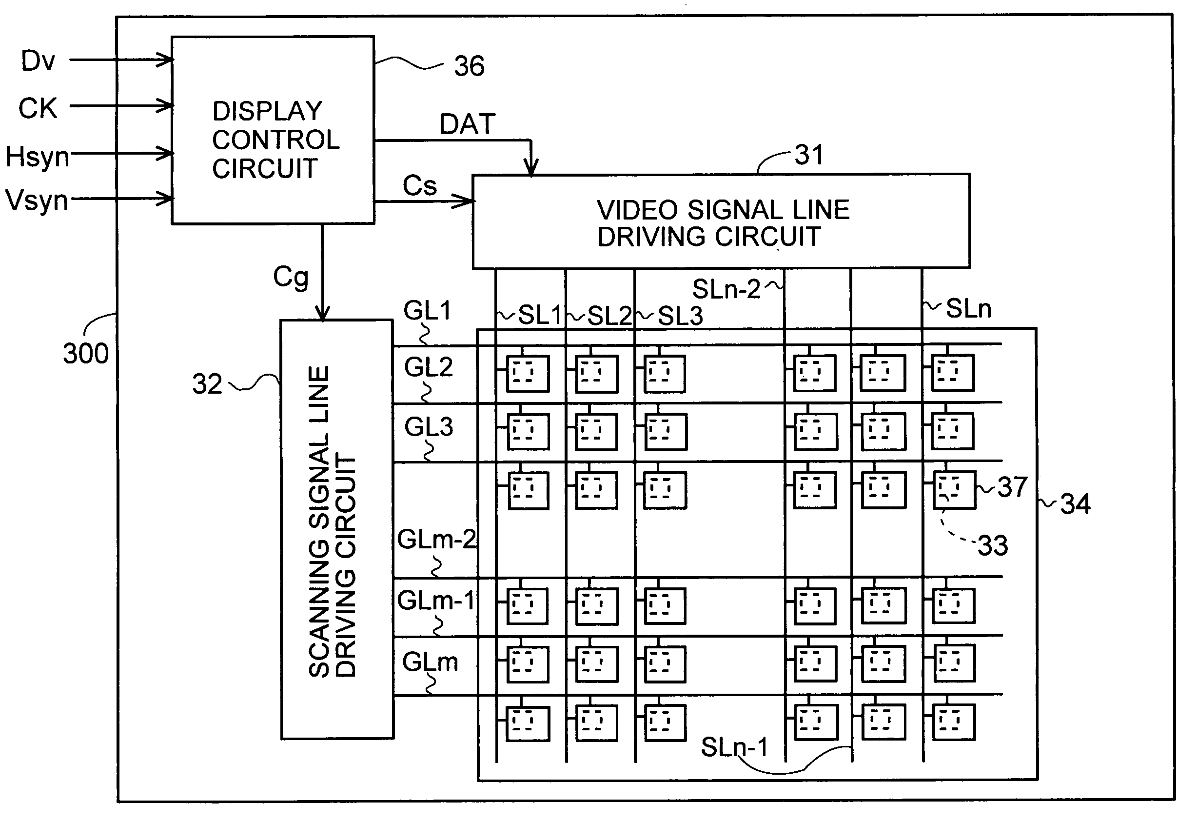
[0055] The following is a description of embodiments of the present invention, with reference to the accompanying drawings. It should be noted that in the following, scanning signal lines to which a video signal is applied whose polarity is inverted from the previous horizontal scanning period are referred to, for convenience's sake, as “polarity-inverted lines” and the pixel formation portions arranged in correspondence to such a “polarity-inverted line” are referred to as “polarity-inverted pixels”. On the other hand, scanning signal lines to which a video signal is applied whose polarity is the same as that of the previous horizontal scanning period are referred to as “polarity-sustained lines” and the pixel formation portions arranged in correspondence to such a “polarity-sustained line” are referred to as “polarity-sustained pixels”. Moreover, the horizontal scanning period immediately after the polarity inversion is referred to as “first horizontal scanning period”, and the ne...


PUM

PropertyMeasurementUnit
voltagesaaaaaaaaaa
widthaaaaaaaaaa
pixel voltageaaaaaaaaaa

Abstract

A horizontal scanning period correction value setting circuit compares a video signal representing a display image of pixel formation portions of polarity-inverted lines and a video signal representing a display image of pixel formation portions of the next row, and generates a signal width correction value for correcting the length of the horizontal scanning period. For this, the signal width correction value is set such that the charge ratios of the pixel formation portions are constant, regardless of a difference between a target voltage of the driving video signals when the polarity is inverted and a target voltage of the driving video signals when the polarity is sustained. Then, a source output control signal and a gate output control signal are generated based on the signal width correction value, and the scanning signals and the driving video signals are generated based on the source output control signal and the gate output control signal.

Description

CROSS REFERENCE TO RELATED APPLICATIONS [0001] This application claims priority under 35 U.S.C. § 119(a) upon Japanese Patent Application No. 2003-391769 titled “LIQUID CRYSTAL DISPLAY DEVICE, DRIVING CIRCUIT AND DRIVING METHOD FOR THE SAME,” filed on Nov. 21, 2003, the entire content of which is hereby incorporated by reference.BACKGROUND OF THE INVENTION [0002] 1. Field of the Invention [0003] The present invention relates to driving circuits and driving methods for liquid crystal display devices, and in particular to multiple line inversion driving in active matrix liquid crystal display devices. [0004] 2. Description of the Related Art [0005] Active matrix liquid crystal display devices provided with TFTs (thin film transistors) as switching elements have been known for several years. Such liquid crystal display devices are provided with a liquid crystal panel which includes two insulating substrates that are arranged opposite one another. On one substrate of the liquid crystal ...

Claims


Application Information

Patent Timeline
Patent Type & Authority Applications(United States)
IPC IPC(8): G02F1/133G02F1/1333G09G3/20G09G3/36
CPCG09G3/3614G09G2310/0205G09G3/3648G02F1/133
Inventor HOSOTANI, YUKIHIKO
Owner SHARP KK
Why Eureka
Try Eureka