Interference cancellation method and apparatus

a technology of interference cancellation and interference, applied in the field of interference cancellation methods, can solve the problems of low system capacity, high error rate, and inability to work well in the receiver structure based on conventional matched filter reception

Inactive Publication Date: 2005-05-26
DESIGN STANDARDS CORP
View PDF15 Cites 91 Cited by
  • Summary
  • Abstract
  • Description
  • Claims
  • Application Information

AI Technical Summary

Problems solved by technology

The drawback is the absence of orthogonality between transmitted signals however results in higher error rates and thus in a lower system capacity.
Receiver structures based of conventional Matched Filter reception do not work well in these scenarios.
Matched Filters alone are not able to separate the interference caused by either the channel disturbance or the use of non-orthogonal codes.
Though this receiver collects more energy in forming its decision variables and thus reduces the underlying bit error rate, the signals meant for different remote terminals may still present substantial interference.
In case the transmitted signal are not originally orthogonal to each other, other more complex techniques need to be employed.
These transmissions cannot be made orthogonal to each other, thus orthogonality between signals transmitted from a single Base Station are of not much help in such situations.
Because of the different propagation delays to different Remote Stations, transmissions from different Base Stations cannot be made orthogonal to each other.
Channel equalizers can be used to orthogonalize receptions from each Base Station, however, they cannot orthogonalize receptions from different Base Stations.
Orthogonalizing receptions from each Base Station and then combining the resulting waveforms in some fashion will provide some gains, however, those gains will be limited since the receiver will in general behave as a RAKE receiver.
The problem will be further exacerbated if the transmissions to different Remote Stations from each Base Station are not originally orthogonal to each other.
A similar problem is encountered when data is transmitted form the Remote Stations to the Base Stations.
If the interference received from Remote Stations operating in neighboring cells cannot be separated from the signal received from in-cell Remote Stations, only a limited amount of improvement can be achieved using any interference reduction techniques.
Since cost is a major factor in any user equipment, complex multi-user interference cancellation schemes have not been proposed for the Remote Stations.
The disadvantages of having a MUD system at a Remote Station are: (a) complexity is a primary bigger issue for Remote Stations; (b) the information on codes used within the cell by other users are not known at a Remote Station; (c) the information on codes used by users in neighboring cells are not known at a Remote Station Removing these disadvantages of the Remote Station will render many MUD algorithms previously applicable only for Base Stations, applicable to the Remote Stations as well.
Either way, the transmission of CCU data is an issue that needs to be addressed optimally.
Due to the high transmission power required to reach the edge of a cell reliably, broadcast type transmissions are very costly in CDMA systems.
Integrating over longer that symbol intervals will increase processing delay and buffering especially for long symbols.
Performing downlink code use estimation utilizing signal presence estimation on different channels could save considerable system capacity at the expense of additional HW complexity at the Remote Station.
The drawback to this option is that in case there are a large number of channels on the downlink, the required processing at the Remote Station could be large.

Method used


Image

  • Interference cancellation method and apparatus
  • Interference cancellation method and apparatus
  • Interference cancellation method and apparatus

Examples


Embodiment Construction

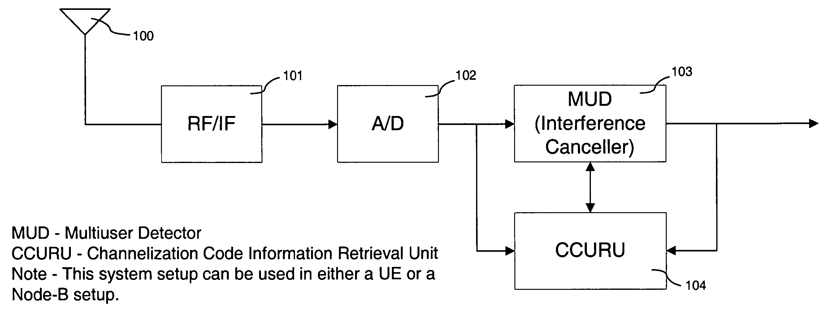
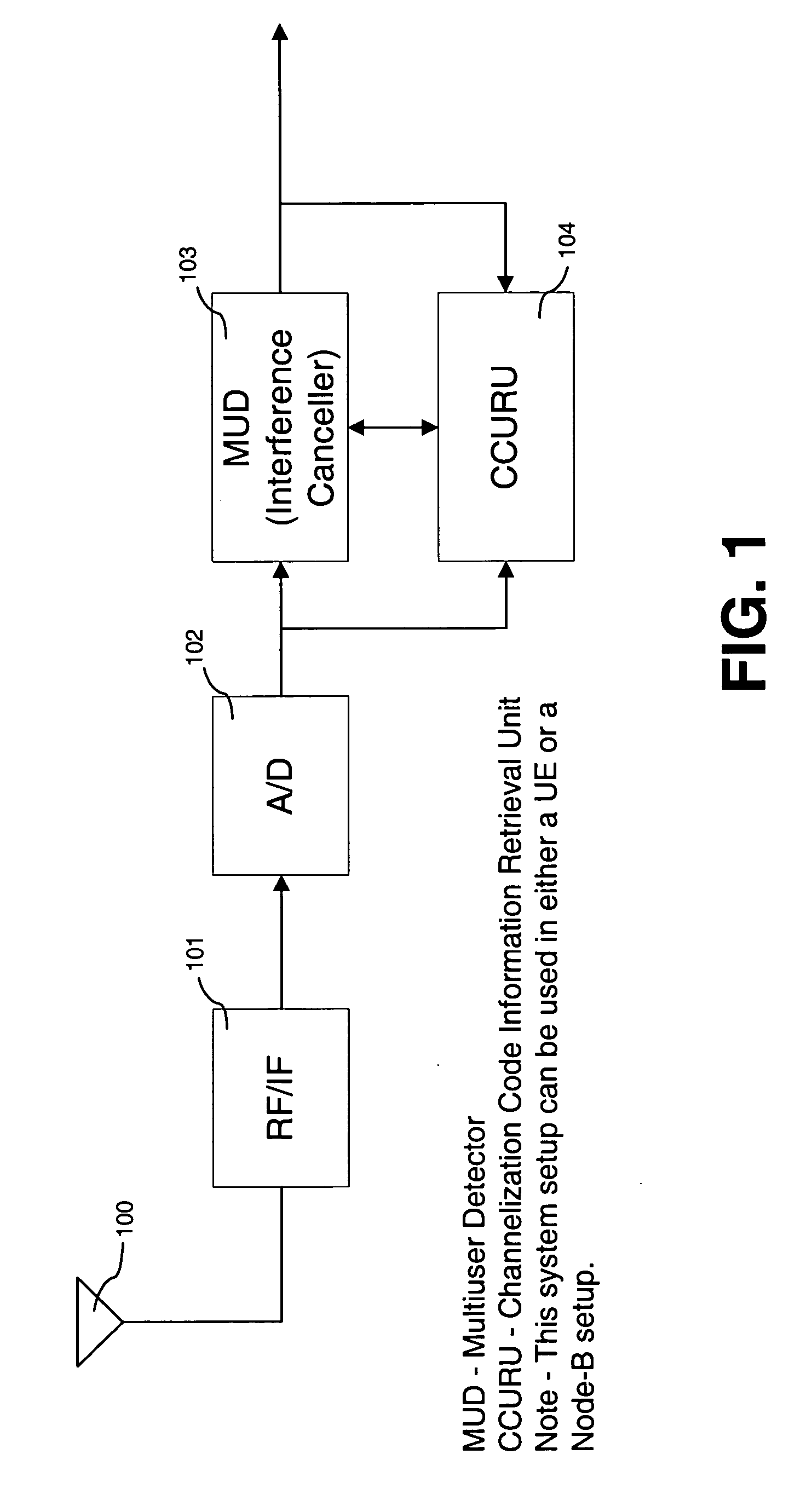
[0023] A general system functional configuration of the disclosed method is shown in FIG. 1. As shown in FIG. 1 there are two main modules required for the system. One is the Multi-User Detector (MUD) 103 module and the CCU Retrieval Unit (CCURU) 104. The received signals at the antenna input 100 are RF filtered 101, Analog to Digital (A / D) 102 converted and then supplied to the MUD 103 and CCURU 104 modules. The connections shown attached to the MUD 103 and CCURU 104 modules are meant to demonstrate the different possible signal flows required to and between the two modules. Depending on the way the system is operated, a certain flow might not be required. The main different ways the system could be operated are a follows:

[0024] (a) Use only the feed-forward CCURU 104 process, where the CCURU 104 is only connected to the output of the A / D converter 102 and has no connection to the MUD 103 output. This necessitates that the CCURU 104 does not rely on MUD 103 processed output signal...


PUM


Abstract

A Multi-User Detection device and method for DS-CDMA to allow enhanced signal reception under Multi-User Interference (MUI) at either the Remote Station or the Base Station is disclosed. The method includes the steps of relaying current channelization code use at Base Stations to Remote Stations operating in the vicinity of the Base Stations. This information is used by an MUD device at the Remote Station, to improve its ability to separate signals transmitted from different Base Stations. The downlink channelization code information is used to recreate the interference received by all neighboring Base Stations transmissions at the Remote Station. The same method can be applied at the Base Station side. The Uplink Channelization Code Usage information is relayed to each Base Station from its neighboring Base Stations. Recreating the total Remote Station interference at the Base Station allows a multistage interference cancellation based MUD to enhance its capability of receiving Remote Stations in its coverage area.

Description

RELATED APPLICATIONS [0001] This application is related and claims the benefits of U.S. provisional patent application APPL No. 60 / 525,088, FILING DATE Nov. 25, 2003 and entitled “Downlink interference cancellation method and apparatus. The content of this provisional application is incorporated herein as reference.BACKGROUND OF THE INVENTION [0002] 1. Technical Field [0003] The present invention relates to an improved interference cancellation method for use in wireless communications systems employing code division multiple access techniques. [0004] 2. Background Art [0005] Code Division Multiple Access (CDMA) communications allow different users to communicate over a common medium at the same time by using user specific codes embedded into their signals in order to differentiate from each other's transmissions. The user codes are normally designed to be orthogonal to each other in time. When CDMA is employed for sending information from a Base Station to Remote Terminals, the cod...

Claims


Application Information

Patent Timeline
Patent Type & Authority Applications(United States)
IPC IPC(8): H04B1/707H04Q7/00
CPCH04B1/71075H04B2201/70702H04B2001/70935
Inventor KANTERAKIS, EMMANUEL
Owner DESIGN STANDARDS CORP
Why Eureka
Try Eureka