Wheel lift that may be rapidly disassembled and converted

a wheel lift and rapid technology, applied in the direction of load-engaging elements, transportation items, item transportation vehicles, etc., can solve the problems of limited wheel lifts, inability to handle, and inability to load, so as to facilitate rapid connection and decoupling, facilitate rapid connection and disassembly, and facilitate rapid field disassembly

Active Publication Date: 2005-05-26
MILLER IND TOWING EQUIP INC
View PDF28 Cites 5 Cited by
  • Summary
  • Abstract
  • Description
  • Claims
  • Application Information

AI Technical Summary

Benefits of technology

[0015] Mechanisms, such as cam locks, bolts, pins, wire, etc. may be employed to facilitate rapid connection and decoupling of each wheel lift apparatus (i.e., the receiver / wheel support member set) from the cross bar. For example, a cam lock with a rotatable handle and a spring-loaded plunger pin may be used to quickly connect and disconnect the receiver from the cross bar. The cylinder rod connection point may also need to be connected or disconnected as well. For this purpose, the distal ends of each cylinder rod may include an aperture for use in coupling each cylinder rod to a receiver. Alternatively, each cylinder rod may consist of two component rods that are connected to each other, e.g., one may be slidable within the other and they be attached using a removable locking pin allowing rapid field disassembly. Preferably, the wheel support members are pivotally attached to the receivers using a pivot pin, for example, which may be prevented from accidental disengagement by use of a retaining mechanism, such as a counter-sunk screw. Parallel plates, lying above and below the cross bar, may but need not be used to facilitate attachment of each wheel support member to the receivers.

Problems solved by technology

While capable of automatically loading automobiles in seconds with ease and permitting operators to remain in the safe environment of their cab, self-loading wheel lifts can only load those automobiles possessing tires.
Such wheel lifts are also limited by their inability to handle the weight of larger trucks and the like.
In the past, the wheel support members of self-loading wheel lifts have not been designed to be removed from the cross bar.
However, the process required to engage a towed vehicle using a conventional wheel lift is considerably longer than with a self-loading wheel lift, and may take ten minutes or longer.
The L-arms are designed to engage points on the towed vehicle from the outside in, limiting their ability to engage tires located adjacent curbs, for example.
While some conventional wheel lifts may be converted from using L-arms to a tool bar, the conversion has been manual and time-consuming, and the L-arms were unable to swing from the inside out, limiting their application.
Additionally, the presence of permanently attached powering mechanisms such as hydraulic cylinders may render it difficult and time-consuming to remove wheel support members and / or receivers from the cross bar.

Method used


Image

  • Wheel lift that may be rapidly disassembled and converted
  • Wheel lift that may be rapidly disassembled and converted
  • Wheel lift that may be rapidly disassembled and converted

Examples


Embodiment Construction

[0029] Set forth below is a description of what are currently believed to be the preferred embodiments and / or best examples of the invention claimed. Future and present alternatives and modifications to these preferred embodiments are contemplated. Any alternatives or modifications which make insubstantial changes in function, in purpose, in structure or in result are intended to be covered by the claims of this patent.

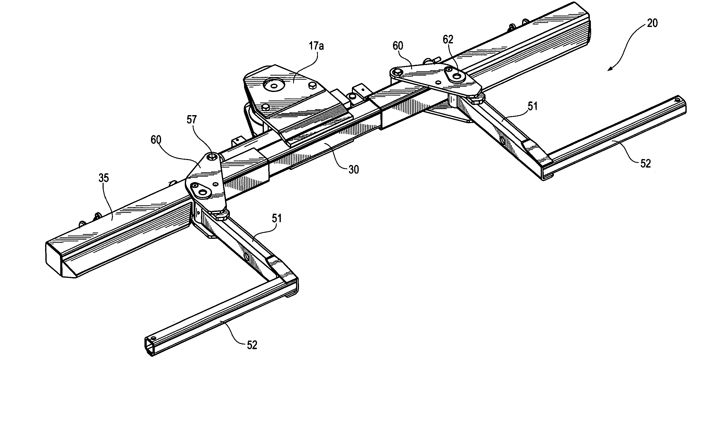
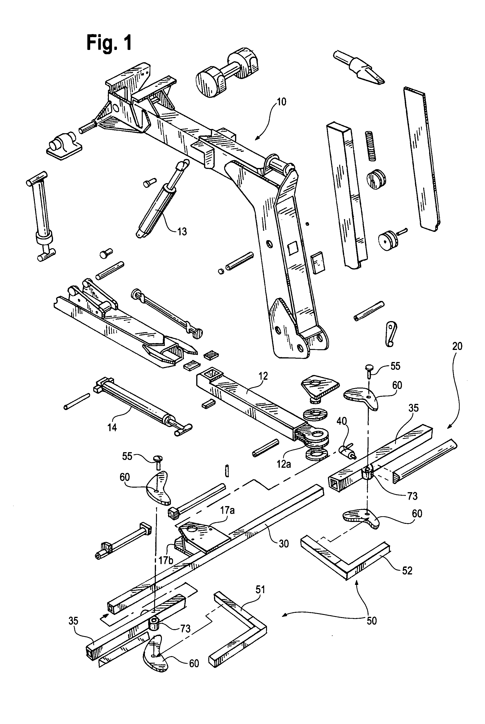
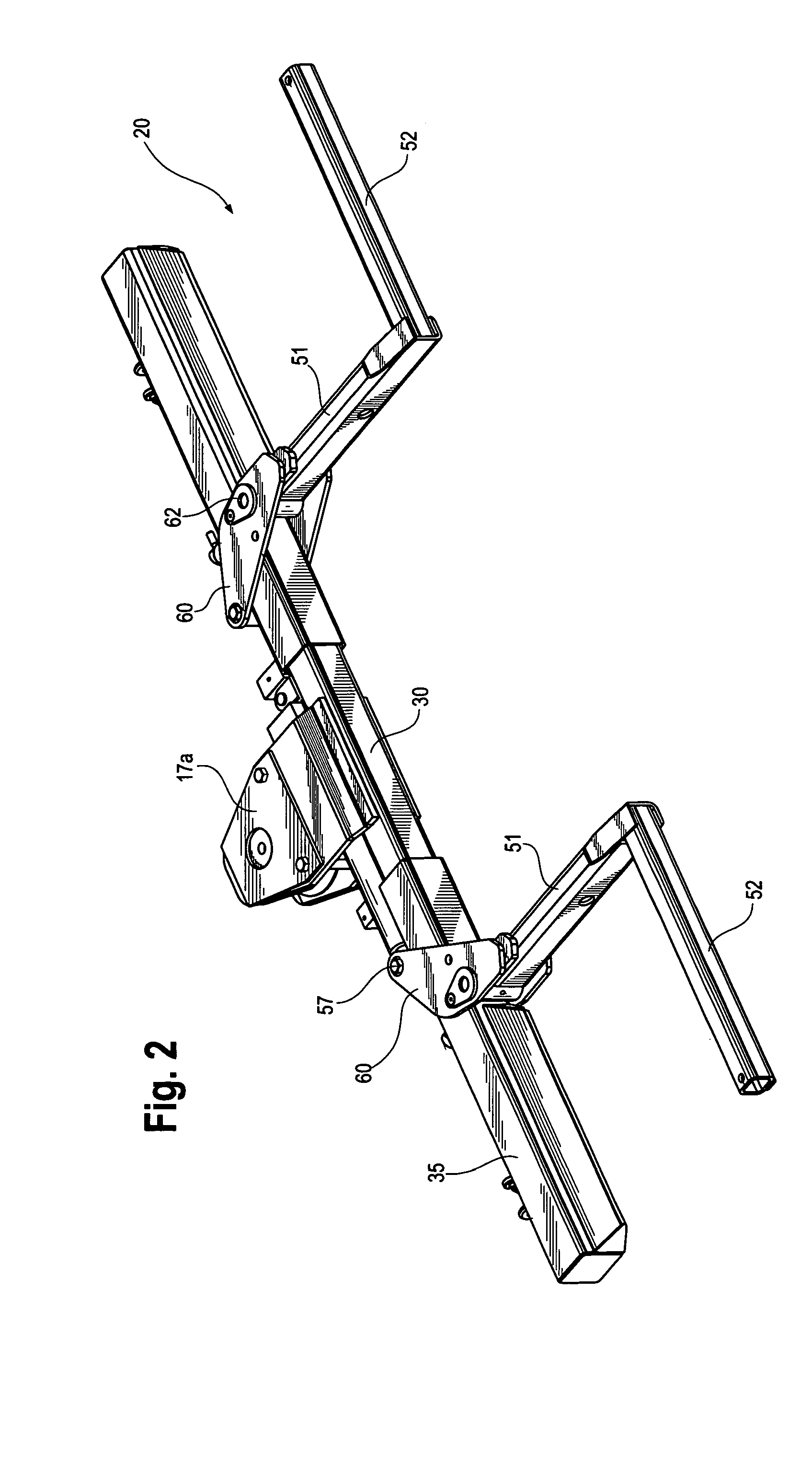
[0030] Referring first to FIG. 1, a preferred embodiment of the self-loading wheel lift of the present invention is shown, designated generally with the reference numeral 20. Wheel lift 20 may but need not be associated with a boom assembly extending rearwardly from a towing vehicle as shown in FIG. 1, which boom assembly may include articulating, hydraulicly powered boom 10, support beam 12, hydraulic boom cylinders 13, 14, and transverse support or cross bar 30, which may be rectangular or curved in cross-section. A distal end 12a of support beam 12 may be pivotall...


PUM


Abstract

A self-loading wheel lift with automatically powered wheel support members, such as L-arms, for engaging the wheels of a vehicle to be towed. The wheel lift may be rapidly disassembled in the field and converted to alternating towing assemblies such as tool bars employing frame fork attachments, hook ends, slings, pintle hooks, fifth-wheel plates, king pins, etc.

Description

BACKGROUND OF THE INVENTION [0001] The present invention generally relates to devices for lifting and towing vehicles by a pair of the vehicle wheels, known as wheel lifts. More particularly, the invention is directed to a self-loading wheel lift that may be rapidly disassembled for transportation or repair and / or rapidly converted or transformed for other applications. [0002] Commonly assigned U.S. Pat. Nos. 4,637,623 and 4,798,509 to Alm, each entitled “Towing Apparatus,” and U.S. Pat. No. 4,836,737 to Holmes entitled “Wheel Lift Tow Assembly,” each disclosing known wheel lift assemblies, as well as U.S. Pat. No. 4,564,207 to Russ et al., entitled “Hydraulic Wheel Lift System For Tow Vehicles,” are each hereby incorporated by reference in their entirety into this application. [0003] For years the standard hydraulic self-loading wheel lift, such as depicted in U.S. Pat. No. 4,564,207 to Russ et al. has enjoyed a specific usage in the towing industry. While capable of automatically ...

Claims


Application Information

Patent Timeline
Patent Type & Authority Applications(United States)
IPC IPC(8): B60P3/12B66C1/00
CPCB60P3/125
Inventor CRAZE, JEAN PAUL
Owner MILLER IND TOWING EQUIP INC
Why Eureka
Try Eureka