Method and apparatus for humidification control of an energy recovery device in a fuel cell power plant

Active Publication Date: 2005-05-26
AUDI AG
View PDF10 Cites 31 Cited by
  • Summary
  • Abstract
  • Description
  • Claims
  • Application Information

AI Technical Summary

Benefits of technology

[0020] In accordance with yet another aspect, performance of the ERD can be controllably degraded by the injection of warm water into the process oxidant inlet stream to raise its dew point and decrease the water transfer from the fuel cell exhaust air stream. This capability may be us

Problems solved by technology

This cools and humidifies the process oxidant inlet stream, which in turn reduces the

Method used


Image

  • Method and apparatus for humidification control of an energy recovery device in a fuel cell power plant
  • Method and apparatus for humidification control of an energy recovery device in a fuel cell power plant
  • Method and apparatus for humidification control of an energy recovery device in a fuel cell power plant

Examples


Example

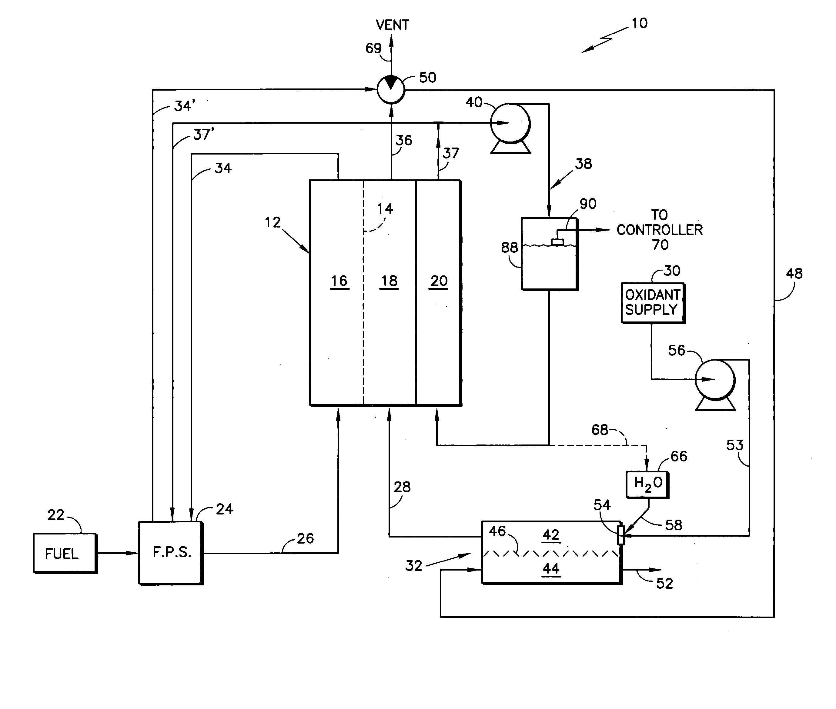
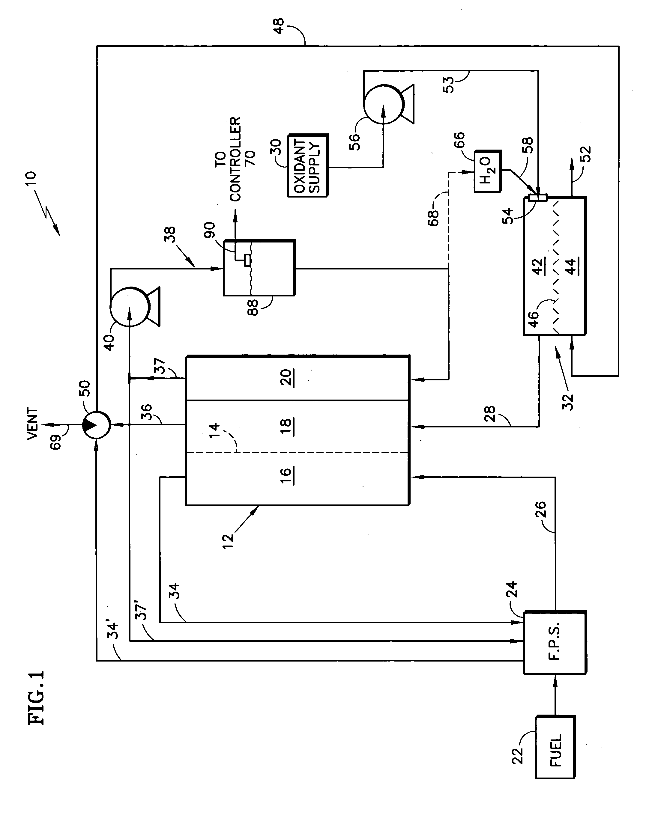
[0024] Referring to the drawings in detail, a fuel cell power plant is shown schematically, very generally, in FIG. 1 and generally designated by reference numeral 10 as a working environment for the present invention. The fuel cell power plant 10 includes at least one fuel cell means for producing electrical energy from a reducing fluid and an oxidant stream, such as fuel cell 12. The fuel cell 12 has an electrolyte 14 such as a proton exchange membrane (PEM), an anode electrode region 16 and cathode electrode region 18 on opposite sides of the electrolyte 14. The fuel cell 12 is typically combined with other virtually identical fuel cells (not shown) in a well known manner to form a fuel cell stack assembly that includes manifolds for directing a reducing fluid and process oxidant stream into and out of the fuel cell 12 in a manner well known in the art. The fuel cell 12 may also include a coolant flow channel or path 20 for removing heat and some excess product water from the fue...


PUM


Abstract

An arrangement is provided in a fuel cell power plant (10) for dispensing (58 74,60, 64) a liquid medium, such as water (66), into a process oxidant (air) stream (53) that flows through one gas channel (42) in an energy recovery device (ERD) (32). An exhaust gas stream (48) containing heat and moisture from the fuel cell (12) flows through another channel (44) in the ERD. An enthalpy exchange barrier (46) separates the one and the other gas channels, but allows mass and/or heat transfer therebetween. The water is injected into the air stream (53) in a controlled (70, 74) amount, and perhaps temperature (78), in response to sensed parameters (80, 84, 90) of the power plant, including the process air stream, to adjust one or more conditions in the power plant. Controlling ERD dryness, providing a defrost capability for the ERD, and/or preventing excessive water accumulation in the system are several of the conditions controlled.

Description

TECHNICAL FIELD [0001] This invention relates to fuel cell power plants, and particularly to the use of an energy recovery device in a fuel cell power plant. More particularly still, the invention relates to control of the mass and / or heat transfer properties of the fuel cell power plant's energy recovery device to enhance water balance and plant energy efficiency. BACKGROUND ART [0002] Fuel cell power plants are commonly used to produce electrical energy from reducing and oxidizing fluids to power electrical apparatus. In such power plants, one or typically a plurality, of planar fuel cells are arranged in a fuel cell stack. Each cell generally includes an anode electrode and a cathode electrode separated by an electrolyte. A reducing fluid such as hydrogen is supplied to the anode electrode, and an oxidant such as oxygen or air is supplied to the cathode electrode. The reducing fluid and the oxidant are typically delivered to and removed from the cell stack via respective manifold...

Claims


Application Information

Patent Timeline
IPC IPC(8): H01MH01M8/04
CPCH01M8/04029H01M8/04134H01M8/04141Y02E60/50H01M8/04164H01M8/04223H01M8/04253H01M8/04156H01M8/04225H01M8/04302
Inventor NUTTALL, BENJAMIN CHARLESDUFNER, BRYAN F.GRASSO, ALBERT P.
Owner AUDI AG
Why Eureka
Try Eureka