Four-blade surgical speculum

a speculum and speculum technology, applied in the field of speculum system, can solve the problems of rigidity of the speculum, damage to the lens of the endoscope, and inaccurate depth of the endoscope, and achieve the effect of effectively illuminated or viewing an area, convenient surgical approach, and convenient inserting of the speculum

Inactive Publication Date: 2005-05-26
OBENCHAIN THEODORE G +1
View PDF77 Cites 79 Cited by
  • Summary
  • Abstract
  • Description
  • Claims
  • Application Information

AI Technical Summary

Benefits of technology

[0012] In this embodiment, one of the handles also includes a coupler for removably coupling a handle of a non-facing blade, so that all of the blades can be coupled together, projecting in a substantially parallel direction. This arrangement of the blades allows a surgeon to dilate a surgical opening in four directions. The blades can extend from the handles linearly or at an angle, so a surgeon's field of vision down the center of the blades is not obstructed.
[0013] In another embodiment, the distance between the facing blades is changeable. By adjusting the distance between the facing blades, the surgeon is able to easily insert the speculum into a narrow surgical opening and then separate the facing blades to dilate that opening. Additionally, the surgeon can adjust the spacing between the different facing blades to most effectively illuminate or view an area of interest.
[0014] In several embodiments, the speculum system facilitates a surgical approach with smaller incisions. Such “minimally invasive surgery” can reduce tissue trauma and post operative pain for the patient, which will facilitate a quicker than normal recovery. Also, this type of surgery may be more cost-effective than traditional open surgical techniques, while permitting safe surgery because all of the relevant anatomical structures can be clearly seen.

Problems solved by technology

However, one of the disadvantages of this approach is that endoscopes do not accurately indicate depth, and surgeons frequently may damage the lens of the endoscope with the surgical instruments or could damage sensitive neurological tissue by feeling around the cavity with the instruments to determine “depth of field.”
The rigidity of this speculum can be a problem, however, as the size and shape of the dilation cannot be easily changed, if at all.
These cottonoid strings may obstruct vision inside of the Michelson speculum and are easily dislodged or snared by the passage of instruments through a rigid speculum.
Stretching and tearing of the muscles can cause inflamation and extreme pain.
This traditional approach to the spine results in denervation of the paraspinous muscles, which may be the reason for some residual post-surgical back pain.
When muscles are denervated, they do not function normally and the biomechanical stability of the spine can be damaged.
Damage to the multifidus muscle thus greatly weakens the structural integrity of the back.
Another disadvantage with these specula is that the specula are not held rigidly in place, either because they are manually held in place or are secured by gripping into bone or other parts of a subjects' body.
Because these specula are not held rigidly in place, the specula cannot be effectively used as a reference point in techniques like image guided surgery.

Method used


Image

  • Four-blade surgical speculum
  • Four-blade surgical speculum
  • Four-blade surgical speculum

Examples


Embodiment Construction

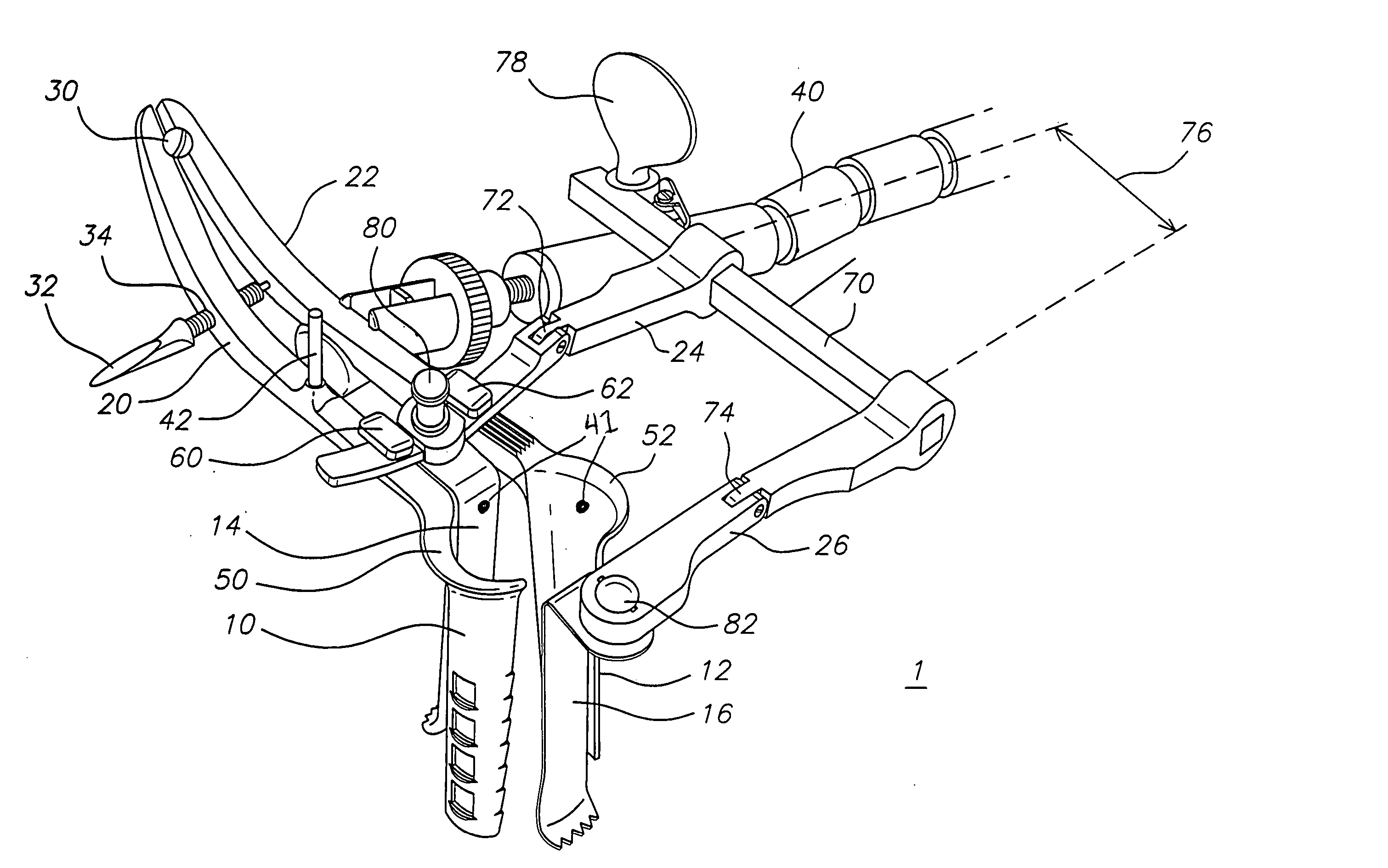
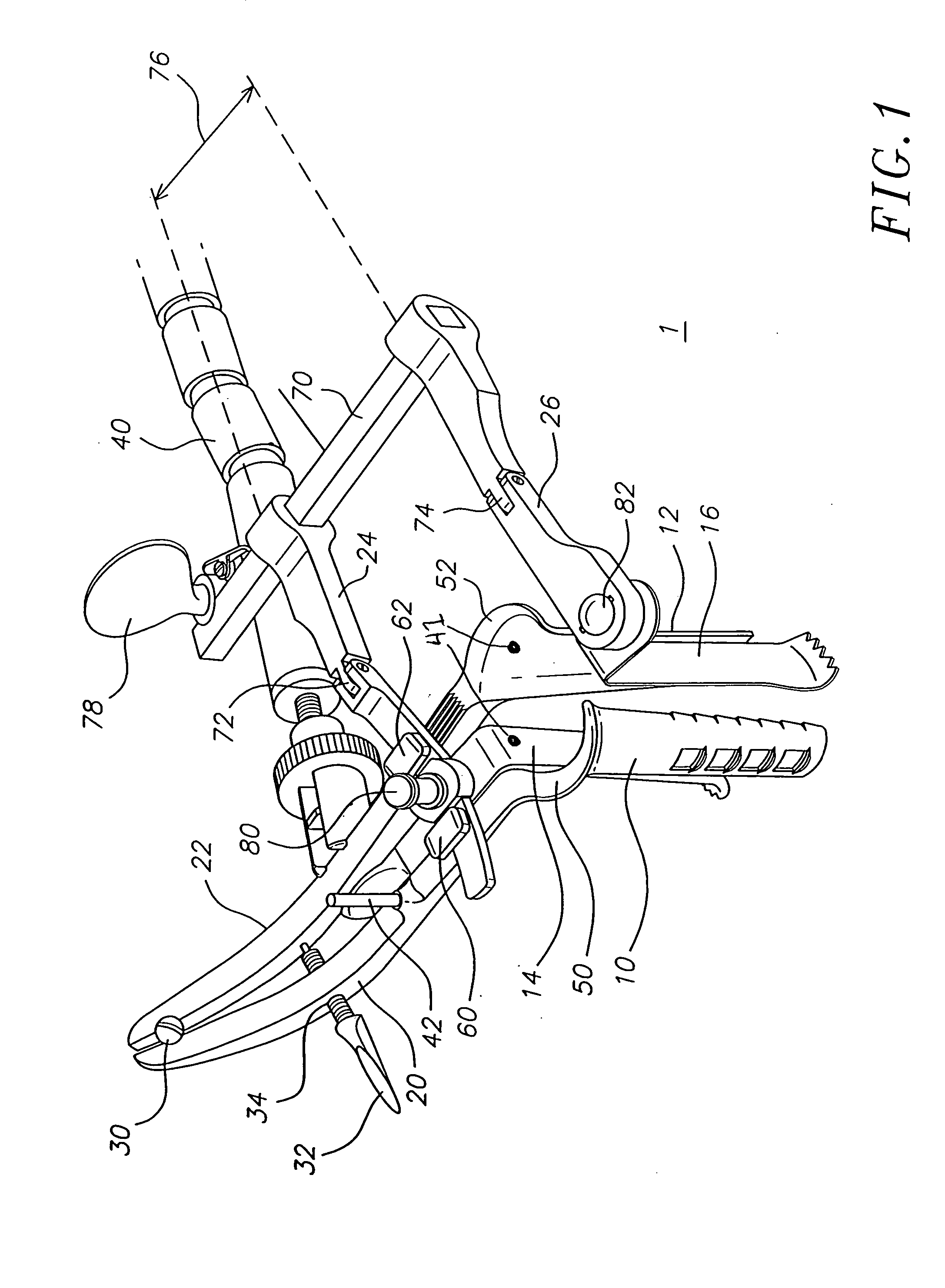
[0019]FIG. 1 shows an embodiment of a speculum system 1 with four blades 10, 12, 14, 16 attached to four handles 20, 22, 24, 26. The first and second handles 20, 22 are attached by a hinge 30 and curve upward. It is also within the scope of this invention for the handles 20, 22 to be straight. Although the handles may be designed with a fixed distance therebetween, in this embodiment, a screw 32 is threaded through a hole 34 in the first handle 20 to push against the adjacent solid surface of the second handle 22. This screw 32 thereby sets a distance between the first and second handles 20, 22. Any other mechanism for distancing the first and second handles 20, 22, such as a latch, variable spacer, or the like can also be used.

[0020] Again, although not required in this embodiment, an optional stabilizing arm 40 grips the second handle 22 to stabilize the speculum system 1 to a fixed position. The stabilizing arm 40 may alternatively grip onto any other suitable portion of the spe...


PUM


Abstract

A speculum system with four blades is provided. The blades project in approximately the same direction, and each blade is connected to a handle linearly or at an angle The handles are coupled together. In one embodiment, the distance between the blades is changeable so that a field of view defined as the viewable area between the blades can be increased or decreased. In another embodiment, the blades include texture, such as ribs, holes or teeth to grip onto surrounding muscle fiber. In yet another embodiment, a stabilizing arm attaches to a stabilizing object, such as a table or heavy or immovable object, and to one of the handles to stabilize the speculum system.

Description

CROSS-REFERENCE TO RELATED APPLICATION(S) [0001] This application is a continuation of allowed application Ser. No. 10 / 337,613 filed Jan. 6, 2003, the disclosures of which are incorporated herein by reference.FIELD OF THE INVENTION [0002] The invention relates to a speculum system, more particularly a surgical speculum system. BACKGROUND OF THE INVENTION [0003] Medical professionals frequently employ specula to view or dilate areas within the body. Specula are well known. The first reference to a speculum occurred in 1597 and related to a device for dilating the eyelids. A century later, oral and vaginal specula were disclosed “wherewith the womb or mouth is dilated or opened.” William A. Smellie describes in his 1752 treatise on midwifery a “speculum matricis” for spreading open the cervix to look into the womb. Nearly a century later, Robert Graves disclosed the Grave's speculum, a bivalve vaginal speculum that is still in use today. By 1862, a catalog produced at an international...

Claims


Application Information

Patent Timeline
Patent Type & Authority Applications(United States)
IPC IPC(8): A61B1/32A61B17/02
CPCA61B17/0206A61B1/32
Inventor OBENCHAIN, THEODORE G.MCKINLEY, LAURENCE M.
Owner OBENCHAIN THEODORE G
Why Eureka
Try Eureka