Device for controlling fluid flow in an aspiration system

a technology of fluid flow and aspiration system, which is applied in the direction of suction devices, suction irrigation systems, eye surgery, etc., can solve the problems of eye damage, eye damage, and eye injury, and achieve the effect of improving the safety and comfort of patients

Inactive Publication Date: 2005-05-26
THE CLEVELAND CLINIC FOUND
View PDF8 Cites 27 Cited by
  • Summary
  • Abstract
  • Description
  • Claims
  • Application Information

AI Technical Summary

Problems solved by technology

A cataract is an opacity of the lens of an eye that results in impaired vision or blindness.
If the aspiration system overwhelms the irrigation system, i.e., removes more fluid than the irrigation system supplies, the fluid pressure in the anterior chamber of the eye may drop and the anterior chamber of the eye may collapse.
A collapse of the anterior chamber of the eye may result in damage to eye structures, such as the cornea, iris, and lens capsule.
However, reduced negative pressure results in a slower, more difficult procedure since the negative pressure is used not only to aspirate the lens fragments but also to hold the portions of the lens to the end portion of the tool and help to breakup the lens material.

Method used


Image

  • Device for controlling fluid flow in an aspiration system
  • Device for controlling fluid flow in an aspiration system
  • Device for controlling fluid flow in an aspiration system

Examples


Embodiment Construction

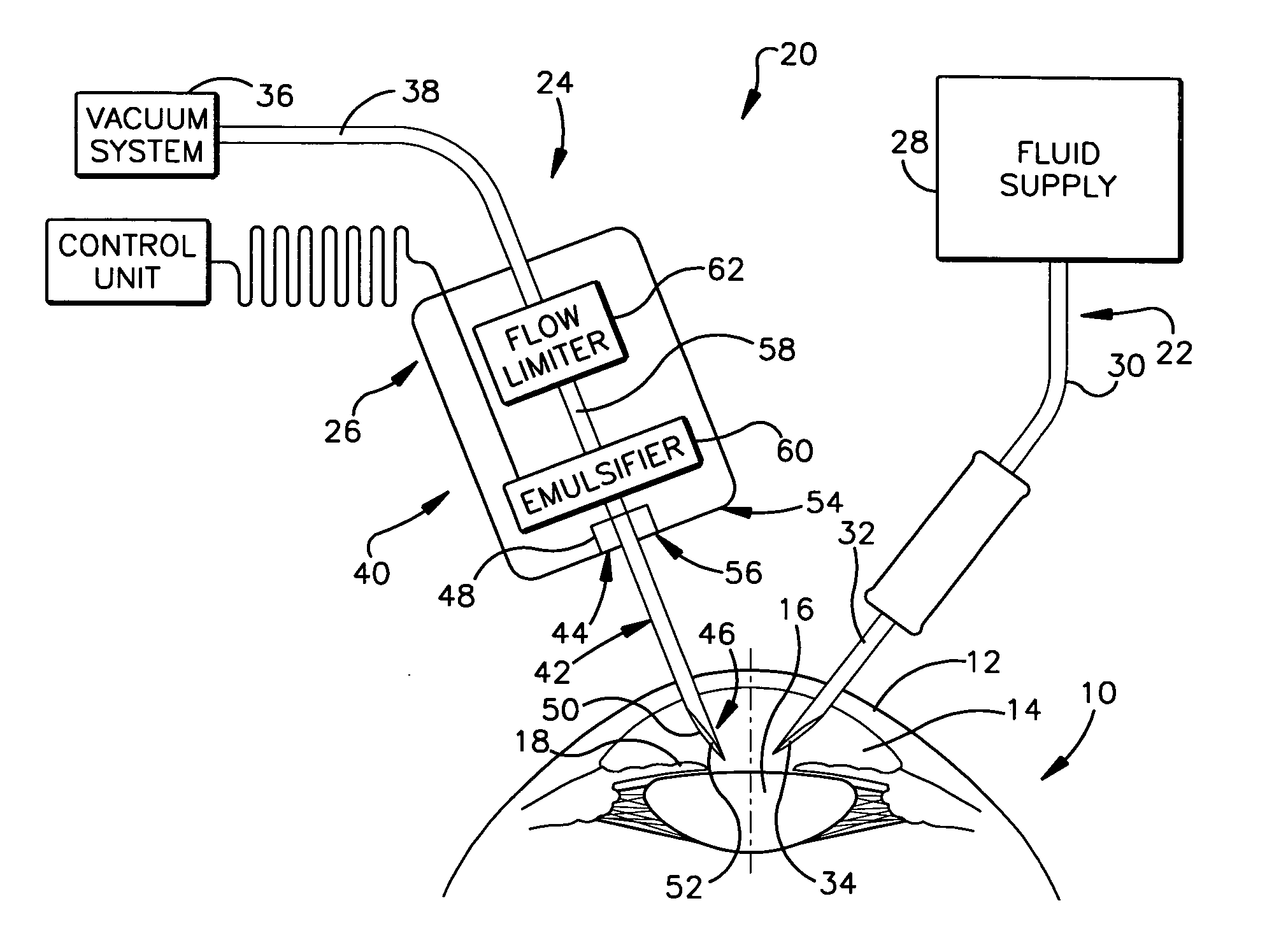
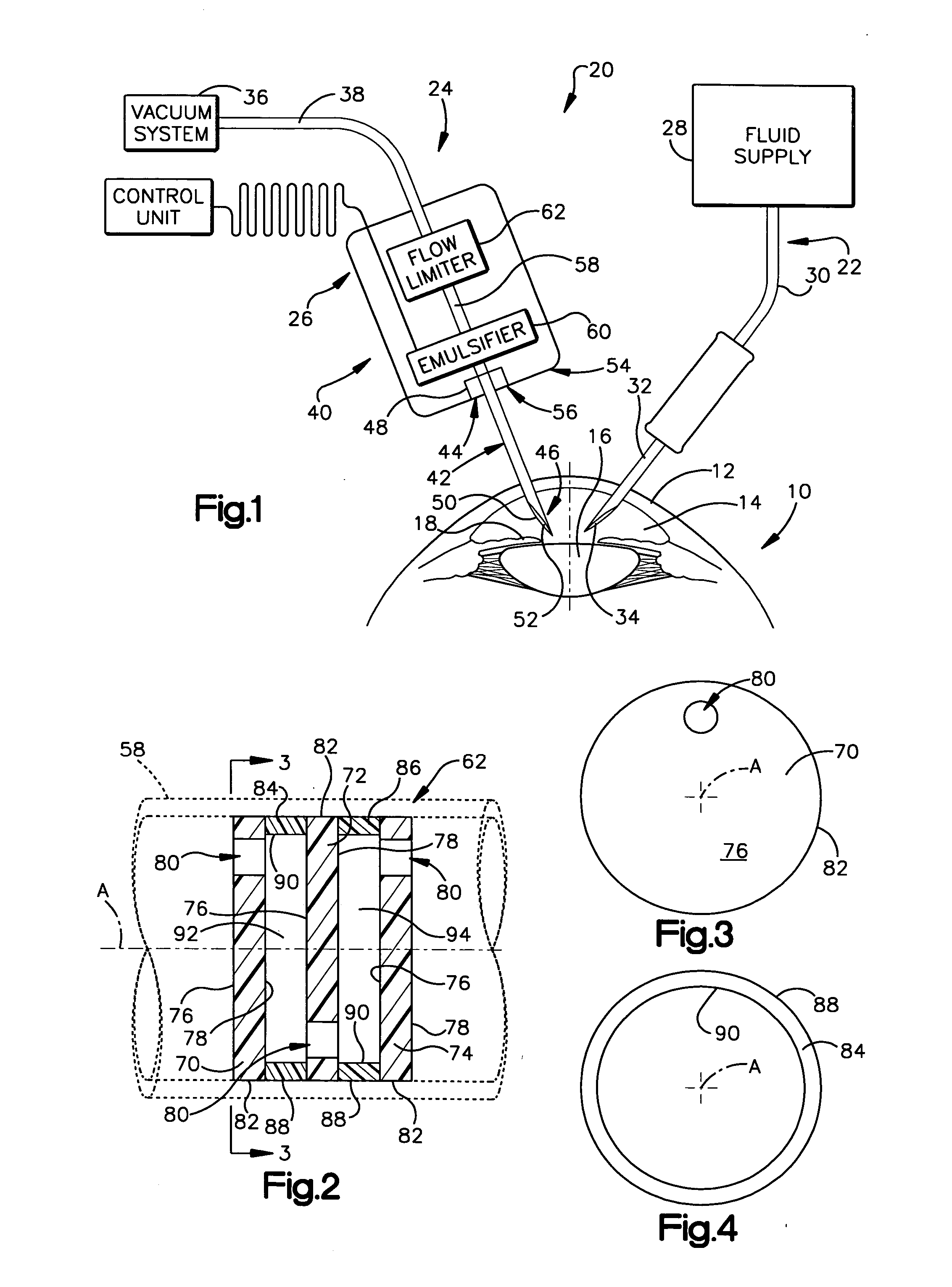
[0018]FIG. 1 illustrates an eye 10. The eye 10 includes a cornea 12 that partially defines a fluid-filled anterior chamber 14 of the eye. A lens 16 and an iris 18 are located within the anterior chamber 14.

[0019]FIG. 1 also illustrates a phacoemulsification system 20 for removing the lens 16 of the eye 10. The phacoemulsification system 20 includes an irrigation system 22, an aspiration system 24, and a phacoemulsification tool 26.

[0020] The irrigation system 22 includes a fluid supply 28, an irrigation conduit 30, and an irrigation needle 32. The fluid supply 28 is preferably saline. The irrigation conduit 30 connects the fluid supply 28 to the irrigation needle 32. The irrigation needle 32 includes a central lumen through which irrigation fluid, e.g., saline, flows. Irrigation fluid exits the lumen of the irrigation needle 32 at an opening 34 located at an end of the needle.

[0021] The aspiration system 24 includes a vacuum system 36 and an aspiration conduit 38. The vacuum syst...


PUM


Abstract

A device for, when connected to a vacuum system, conducting aspiration fluid away from a surgical site includes a conduit having a portion adapted for insertion into the surgical site. The device also includes a flow limiter interposed between the vacuum system and the conduit and in fluid communication with the conduit. The flow limiter has at least two orifices arranged in series and a flow path interconnecting the at least two orifices. The flow path has a flow area that is greater than a flow area of each one of the at least two orifices. Aspiration fluid flows through the conduit and the flow limiter in response to a pressure drop between the surgical site and the vacuum system. The flow limiter produces a non-linear relationship between a rate of aspiration fluid flow and the pressure drop.

Description

RELATED APPLICATIONS [0001] This application claims the benefit of U.S. Provisional Application Nos. 60 / 511,442, filed Oct. 15, 2003 and 60 / 513,493, filed Oct. 22, 2003 and is incorporated herein by reference.TECHNICAL FIELD [0002] The present invention relates to a device for controlling fluid flow in an aspiration system. More particularly, the present invention relates to a device for controlling fluid flow in an aspiration system for use during phacoemulsification. BACKGROUND OF THE INVENTION [0003] A cataract is an opacity of the lens of an eye that results in impaired vision or blindness. Phacoemulsification is a surgical procedure in which nucleus, epinuclear material, and cortical material, are removed from the lens. After phacoemulsification is performed, only the lens capsule of the lens remains in the eye. During phacoemulsification, an incision is made in the cornea of the eye. An end portion of a tool is inserted into the fluid-filled anterior chamber of the eye. The in...

Claims


Application Information

Patent Timeline
Patent Type & Authority Applications(United States)
IPC IPC(8): A61F9/007A61M1/00
CPCA61F9/00736A61M1/0064A61M1/0031A61M1/774A61M1/74
Inventor HUANG, DAVIDHALL, JOHN D.GOODIN, MARK S.THOMPSON, DAVID L.
Owner THE CLEVELAND CLINIC FOUND
Why Eureka
Try Eureka