System and method for cooling multiple logic modules

a logic module and cooling system technology, applied in the field of system and method for cooling multiple logic modules, can solve the problems of significant increase in temperature of specific logic components within a server, and dramatic drop in the quantity of airflow providing cooling air, so as to optimize server performance and maximize clock speed and server performance, without risk of circuit failure

Inactive Publication Date: 2005-06-02
IBM CORP
View PDF16 Cites 57 Cited by
  • Summary
  • Abstract
  • Description
  • Claims
  • Application Information

AI Technical Summary

Benefits of technology

[0007] The shortcomings of the prior art are overcome and additional advantages are provided through the provision of continually monitoring and controlling the temperature of all logic modules and of adjusting at least one of the voltage and the clock speed accordingly to maximize clock speeds and server performance for the given temperature conditions that the cooling solution is able to provide at any m

Problems solved by technology

There are many circumstances where the cooling of CMOS logic circuits may degrade resulting in substantially higher operational junction temperatures.
There are numerous ways the temperature of specific logic components within a server may substantially increase in temperature; such as when air cooling and the ambient temperature rises dramatically as in the case of a failed air conditioning system; such as when the thermal conductive path between the logic devices and convective surfaces experience an increase in thermal resistance due to degradation of the thermal properties of the conductive path or improper assembly; such as when the quantity of airflow providing the air cooling drops dramatically due to debris clogging the fins of a heat sink or a fan failure;

Method used


Image

  • System and method for cooling multiple logic modules
  • System and method for cooling multiple logic modules
  • System and method for cooling multiple logic modules

Examples


Embodiment Construction

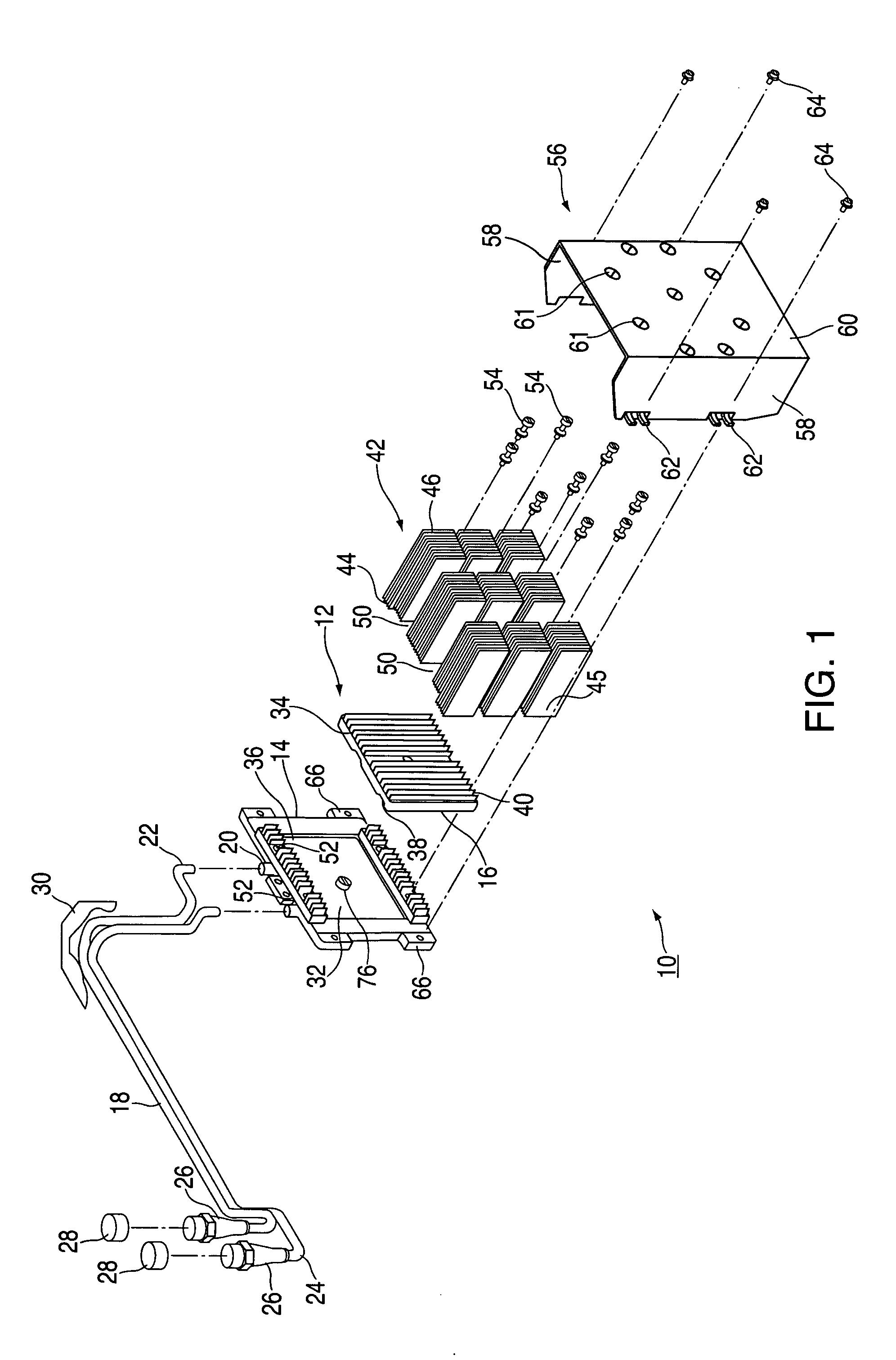
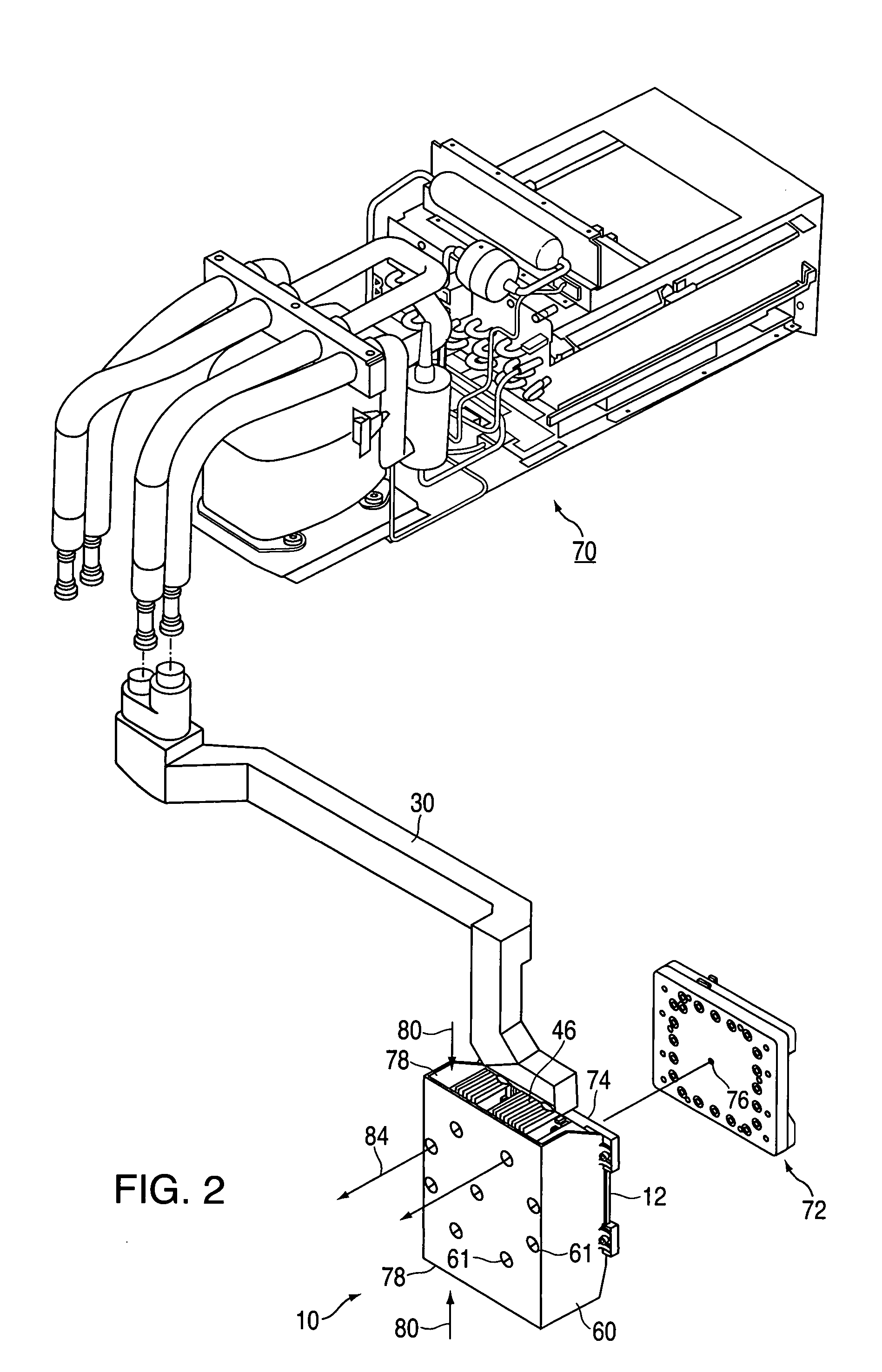
[0022] Referring to FIG. 1, an exemplary embodiment of an integrated cooling unit is shown generally at 10 and is hereinafter referred to as “cooling unit 10.” Cooling unit 10 provides for the removal of heat from electronic circuitry via circulation of a liquid coolant and the dissipation of the removed heat via forced convection of air. The circulation of the liquid coolant allows heat to be transferred to the coolant and subsequently removed by a fan, for example, that forces air over the circulating coolant. Although cooling unit 10 is described as being incorporable into computer-based applications in which heat is removed from electronic circuitry and dissipated through a fluid medium, it should be understood by those of skill in the art that cooling unit 10 may be utilized in other applications in which heat is generated and is to be dissipated to the surrounding environment. Furthermore, although cooling unit 10 is utilizes refrigerant R134A in a preferred embodiment as the ...


PUM


Abstract

A method and system of cooling hardware, sensing hardware, and supporting code streams that enables a non-redundant liquid cooling system to be used seemlessly in conjunction with an air cooling backup solution. The result offers system speed and reliability benefits of liquid cooling except for the brief occasions when the primary cooling system has failed and air cooling takes over. Until the liquid cooling is repaired, system clocks are automatically slowed to be compatible with the circuit speeds possible at the higher temperatures associated with air cooling. When the liquid cooling is repaired, the system clocks are automatically returned to their normal fast state. Depending on the circuit technology used, a supplied voltage may be varied while being air cooled.

Description

FIELD OF THE INVENTION [0001] This invention relates to a system and method to optimally match and adjust clock speed to specific circuit temperatures and voltage conditions present at any given moment in a liquid cooled system for cooling multiple logic modules. BACKGROUND OF THE INVENTION [0002] There are many circumstances where the cooling of CMOS logic circuits may degrade resulting in substantially higher operational junction temperatures. The temperature increase may be sufficient that the speed of the circuits and wiring reliably switch only if the clocks governing the switching speeds of these circuits are slowed. [0003] There are numerous ways the temperature of specific logic components within a server may substantially increase in temperature; such as when air cooling and the ambient temperature rises dramatically as in the case of a failed air conditioning system; such as when the thermal conductive path between the logic devices and convective surfaces experience an in...

Claims


Application Information

Patent Timeline
IPC IPC(8): F25B5/02F25B49/02H01L23/34H01L23/467H05K7/20
CPCF25B5/02Y02B60/1217F25B49/027F25B2600/0253F25B2600/111F25B2700/21161F25B2700/21162F25B2700/21163F25B2700/2117F25B2700/21174F25B2700/21175H01L23/34H01L23/467H05K7/20827H05K7/20836Y02B30/741Y02B30/743G06F1/206G06F1/324G06F1/3296H01L2924/0002F25B49/02H01L2924/00Y02B30/70Y02D10/00
Inventor GOTH, GARY F.KEARNEY, DANIEL J.LOW, KEVIN P.MEYER, UDO H. G.SWANEY, SCOTT B.
Owner IBM CORP
Why Eureka
Try Eureka