Method and apparatus for degassing coating liquid

a coating liquid and method technology, applied in liquid degasification, separation processes, coatings, etc., can solve problems such as problems that cannot be solved, and good and uniform coating films cannot be formed, so as to prevent bubble defects

Active Publication Date: 2005-06-02
FUJIFILM CORP +1
View PDF0 Cites 12 Cited by
  • Summary
  • Abstract
  • Description
  • Claims
  • Application Information

AI Technical Summary

Benefits of technology

[0021] The present invention is made in view of these circumstances. It is an object of the present invention to provide a method and apparatus for degassing a coating liquid which method and apparatus are suitable for forming a good and uniform coat film by preventing bubble defects caused by air bubbles contained in the coating liquid during a step in which a coating apparatus is used to coat a support with a liquid such as a photosensitive material coating liquid.
[0022] It is another object of the present invention to provide a method and apparatus for degassing a coating liquid of high viscosity which method and apparatus can effectively remove air bubbles from the coating liquid in a short time if the degassing process speed per unit time is high.
[0023] It is another object of the present invention to provide a method and apparatus for degassing a coating liquid which method and apparatus can suppress damage to the coating liquid caused by a shock wave resulting from the disappearance of the cavitation as well as corrosion in piping through which the coating liquid is transferred, while inhibiting re-precipitation of a gas dissolved in the surrounding liquid which re-precipitation is caused by a local reaction field resulting from the disappearance of the cavitation.

Problems solved by technology

When the coating liquid containing air bubbles is supplied to a coating apparatus, then coated on a support using the apparatus, and dried, bubble defects such as bubble traces or pin holes are likely to occur in the coat film.
Consequently, a good and uniform coat film cannot be formed.
However, there remain problems that cannot be solved by the various proposals using ultrasonic waves.
1) The air bubbles in the coating liquid cannot be sufficiently removed.
3) The coating liquid is damaged or piping through which the coating liquid is transferred is corroded.
5) A combination of supersonic waves with another degassing method results in an increase in the size of the apparatus.
A coating liquid such as a photographic sensitive coating liquid which contains various additives is originally likely to become frothy and is prone to contain air bubbles.
Accordingly, although various degassing methods and apparatuses have been proposed, these conventional methods still have an insufficient degassing capability.
One of the reasons for the insufficient degassing capability is that when a liquid accommodated in a degassing container is irradiated with ultrasonic waves at a fixed oscillation frequency, ultrasonic vibration causes a fixed compressional wave to be formed.
The standing wave creates problems; air bubbles in the liquid are trapped in a particular area to prevent the bubbles from floating, or the standing wave degrades the capability of dissolving and eliminating fine air bubbles.
As a result, air bubbles cannot be removed effectively.
However, these configurations can increase the quantity of ultrasonic waves applied per unit area of the degassing container to improve degassing efficiency, but fail to eliminate the standing wave.
It is thus difficult for these proposals to efficiently and perfectly remove air bubbles from the liquid.
However, the degassing achieved by this configuration may be insufficient depending on the physical properties of the liquid and a degassing process speed per unit time.
However, an excessive increase in the output of ultrasonic waves causes fine air bubbles of negative pressure, that is, cavitation to be instantaneously generated in the liquid and then disappear.
This phenomenon is likely to occur if the output of ultrasonic waves is excessively increased and if the degassing process speed per unit area is low.
In the conventional ultrasonic degassing apparatus, as already described, when the cavitation disappears, a shock wave is generated which instantaneously forms a local reaction field estimated to have a pressure of 87,000 atm and a temperature of 160,000° C. Thus, the coating liquid may be damaged or piping through which the coating liquid is transferred may be corroded.
In the conventional ultrasonic degassing apparatus, bubbles are likely to precipitate in the case of insufficient degassing and an excessive increase in the output of ultrasonic waves.
However, the degassing may still be insufficient depending on the physical properties of the liquid and the degassing process speed per unit time.
Thus, disadvantageously, the output of ultrasonic waves for each physical property of the liquid must be individually set in view of the degassing process speed per unit time.
However, since the same container must undergo a plurality of steps, the degassing process requires a long time.
Further, disadvantageously, the size of the apparatus must be increased.

Method used


Image

  • Method and apparatus for degassing coating liquid
  • Method and apparatus for degassing coating liquid
  • Method and apparatus for degassing coating liquid

Examples


examples

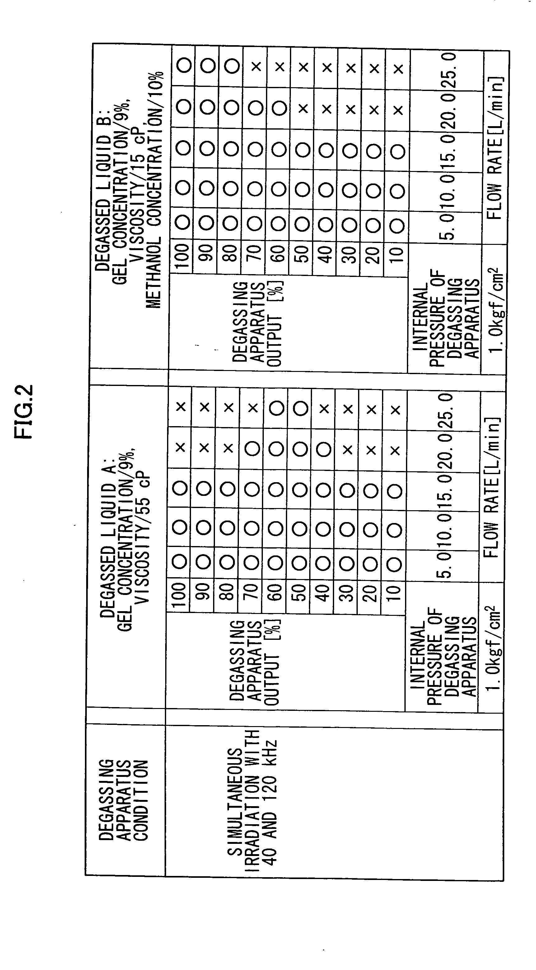
[0057] In the description below, an example of the present invention will be compared with a comparative example.

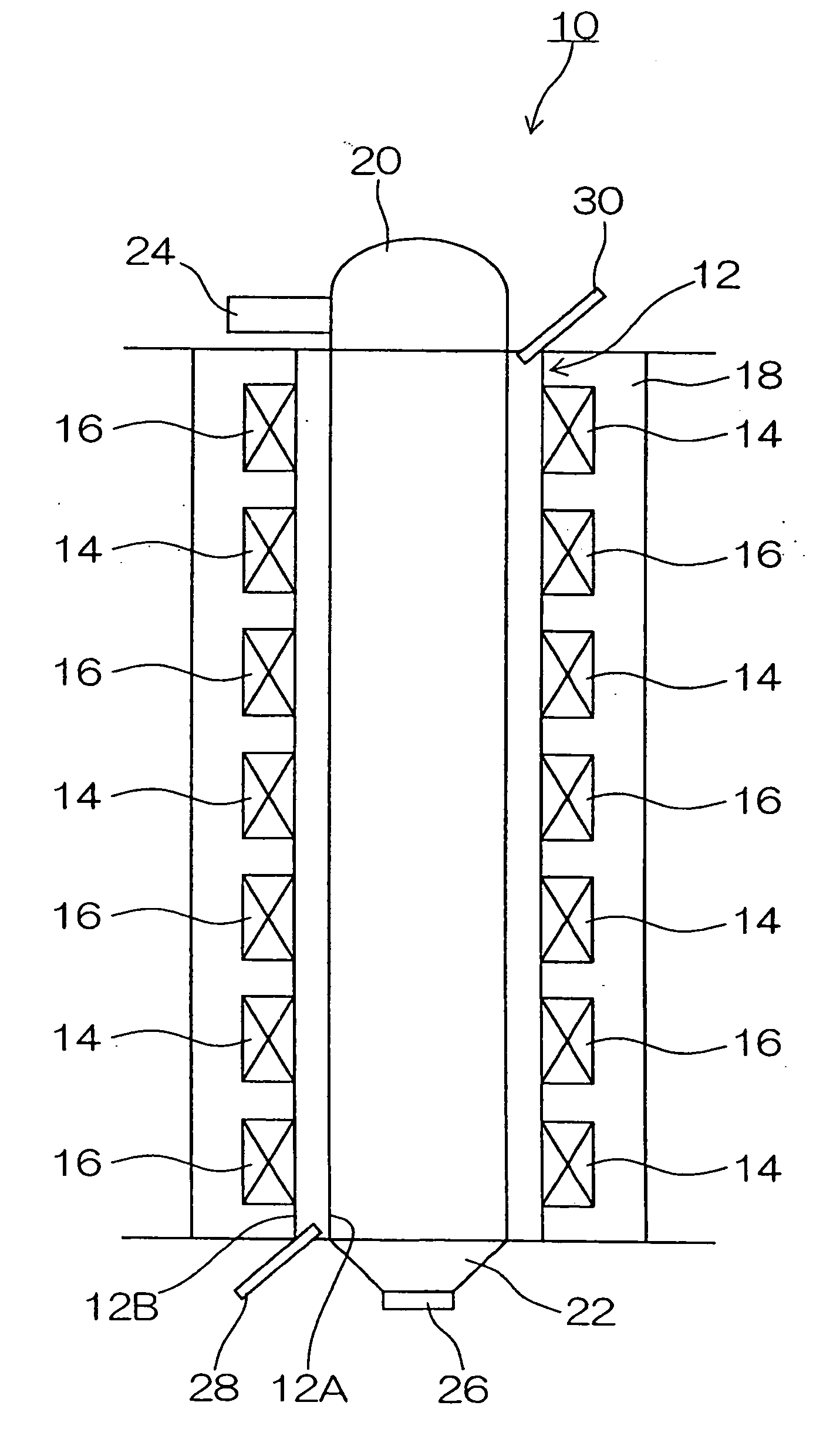
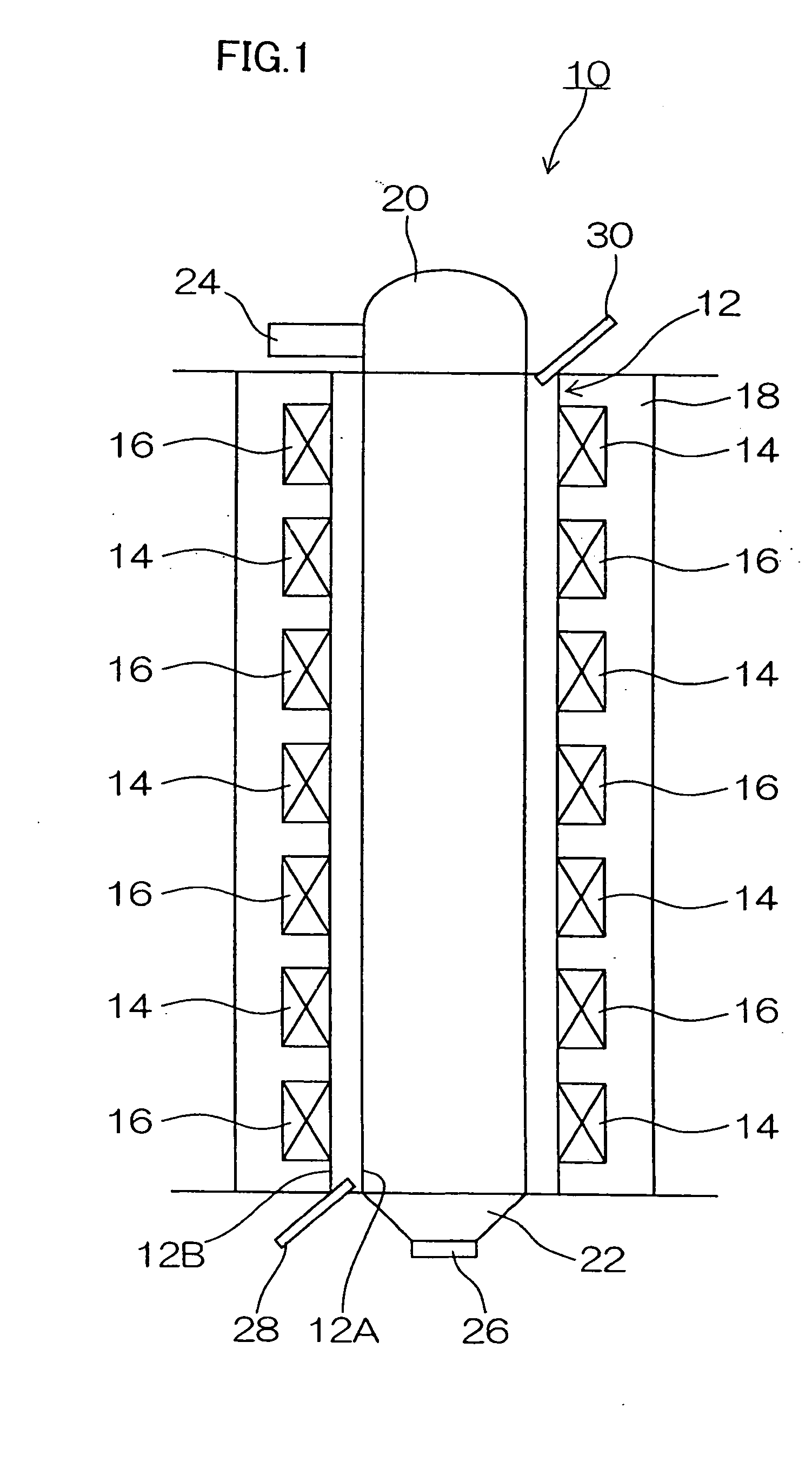
[0058] The coating liquid degassing apparatus 10 configured as shown in FIG. 1 was used in both example and comparative example. As already described, in the example, the ultrasonic vibrators 14 had an oscillation frequency of 40 kHz, while the ultrasonic vibrators 16 had an oscillation frequency of 120 kHz. In the comparative example, the ultrasonic vibrators 14 and 16 had an oscillation frequency of 40 or 120 kHz.

[0059] The maximum total output of ultrasonic waves was 1,500 W in both example and comparative example. The total output was varied at 10% increments up to 10 to 100% of the maximum value.

[0060] The inner pipe 12A had an inner diameter of 124 mm and a length of 845 mm. A uniform pressure (liquid pressure) of 98 kPa (1.0 kgf / cm2) was exerted on the interior of the inner pipe 12A.

[0061] A flow rate of the coating liquid is varied from 5.0 to 25.0 liter per m...


PUM

PropertyMeasurementUnit
pressureaaaaaaaaaa
internal pressureaaaaaaaaaa
oscillation frequenciesaaaaaaaaaa

Abstract

A method of degassing a coating liquid, comprising the step of: irradiating the coating liquid with a plurality of ultrasonic waves of different frequency bands simultaneously to degass said coating liquid.

Description

BACKGROUND OF THE INVENTION [0001] 1. Field of the Invention [0002] The present invention relates to a method and apparatus for degassing a coating liquid, and in particular, to a method and apparatus for degassing a coating liquid, which is suitable for degassing a photosensitive material coating liquid, a heat development photosensitive material coating liquid, a transparent heat-sensitive material coating liquid, an organic solvent coating liquid, or the like. [0003] 2. Description of the Related Art [0004] In general, in a coating liquid used to coat a support with various liquids, air bubbles are likely to be generated during an operation such as agitation, dispersion, or dispensation which is performed before a coating step. When the coating liquid containing air bubbles is supplied to a coating apparatus, then coated on a support using the apparatus, and dried, bubble defects such as bubble traces or pin holes are likely to occur in the coat film. Consequently, a good and uni...

Claims


Application Information

Patent Timeline
Patent Type & Authority Applications(United States)
IPC IPC(8): B01D19/00G03C1/74B05D3/12G03C1/498
CPCB01D19/0078
Inventor YAMADA, HITOSHI
Owner FUJIFILM CORP
Why Eureka
Try Eureka