Internal combustion engine and gasket therefor

a technology of internal combustion engine and gasket, which is applied in the direction of engine seals, auxillary lubrication, sealing arrangements, etc., can solve the problems of increasing the orifice in the wall of the cylinder head, the upper surface of the joint surface of the cam cover is not flat, and the manufacturing of the cam cover to this design is therefore very complicated, so as to prevent the projection from shifting sideways, effective sealing action, and preventing the effect of projection shifting

Inactive Publication Date: 2005-06-02
INT ENGINE INTPROP CO LLC
View PDF1 Cites 10 Cited by
  • Summary
  • Abstract
  • Description
  • Claims
  • Application Information

AI Technical Summary

Benefits of technology

[0012] For example, side-face projecting lips may be provided on both side faces of the projection, which laterally locate round the edges of the co-operating cut-out. Consequently, the wall of the cylinder head is engaged in this region, enabling the gasket to be even more reliably positioned and secured in this region. The resultant positive fit between the projection and the edges of the cut-out reliably prevents the projection from shifting sideways.
[0013] It is also of advantage if the at least one lip is disposed on the projection in the region where the projection is at its maximum projected distance. Since this region is the farthest away from the points between the joint surfaces on the cam cover and on the cylinder head across which the gasket stretches, it is susceptible to a higher risk of being dislodged from its intended position; consequently, the fact of especially providing the at least one lip in this region offers a particularly reliable way of preventing the projection from shifting.
[0014] In an alternative embodiment, two lips may be provided on each of the two side faces of the projection, disposed symmetrically with respect to the region where the projection is at its maximum projection distance, thereby providing a total of four points at which the projection is retained on the cut-out. This offers a particularly reliable means of positioning the projection in the cut-out.
[0015] In another alternative embodiment, the at least one lip extends across the entire projection along the associated side face, producing an uninterrupted positive fit in the entire region of the projection. This provides an extremely reliable way of retaining the projection in its position and a particularly effective sealing action.

Problems solved by technology

However, this means that there are additional orifices in the wall of the cylinder head, which then have to be closed and sealed.
However, the disadvantage of this approach was found to be the fact that the upper surface of the joint surface of the cam cover was not flat as a result.
Manufacturing the cam cover to this design was therefore made very much more complicated.
In addition, making the groove for the sealing lip turned out to be especially complex because it must conform to the contour of the joint surface on the cam cover if the sealing effect is to be reliable.
The gasket itself was also more difficult to make as a result of this design and the required leak-tight seal of the arrangement can therefore be impaired as a result of the complex design of the gasket.

Method used


Image

  • Internal combustion engine and gasket therefor
  • Internal combustion engine and gasket therefor
  • Internal combustion engine and gasket therefor

Examples


Embodiment Construction

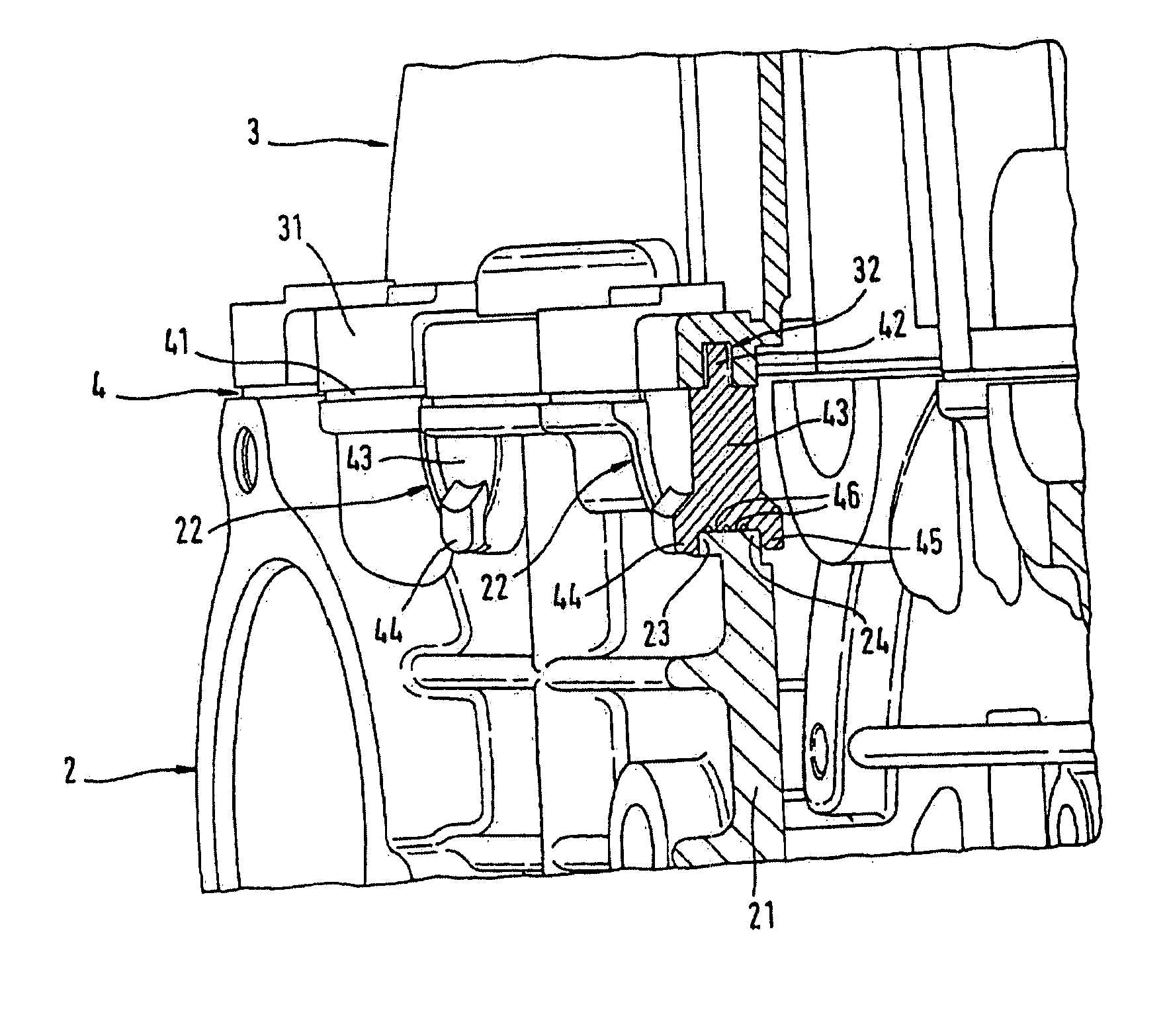
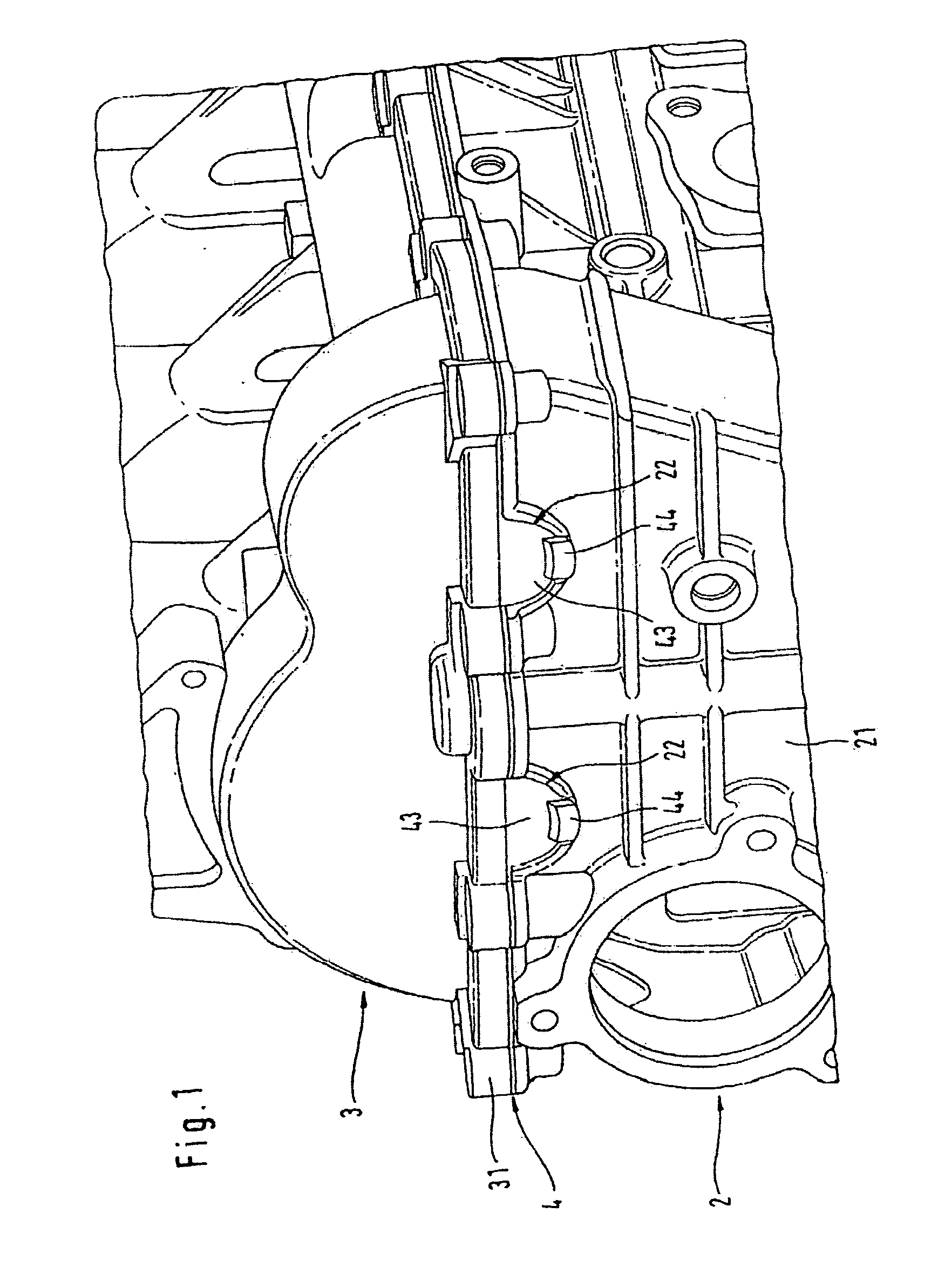
[0021] The diagrams given in the drawings show an internal combustion engine with a cylinder head 2, a cam cover 3 and a gasket 4 disposed in between.

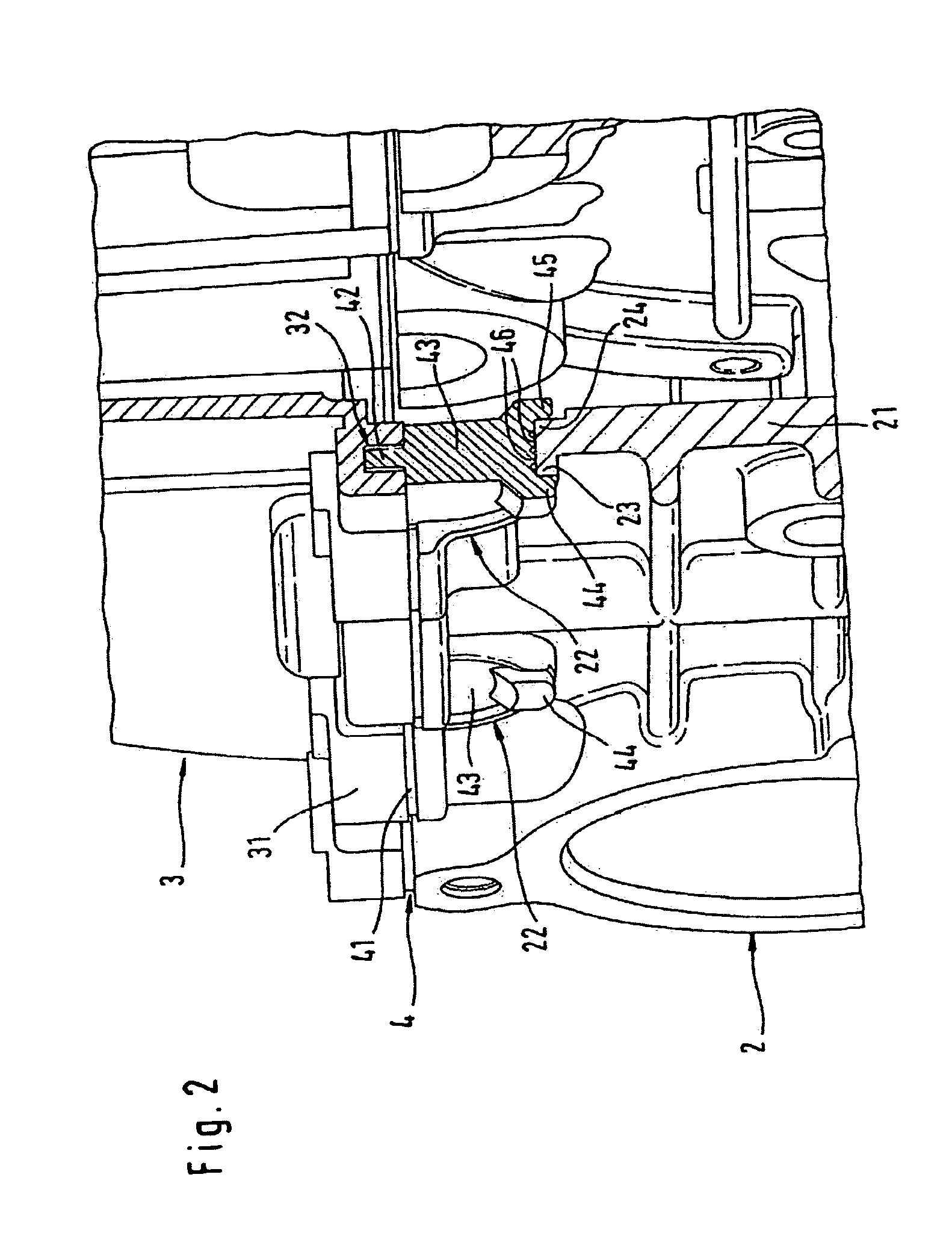
[0022] The cylinder head 2 incorporates a wall 21, in which two cut-outs 22 of a substantially semi-circular shape are provided in this particular embodiment, extending through the wall 21. Matching cut-outs are also provided on the oppositely lying side of the cylinder head 2 (not shown). The cut-outs 22 extend through the wall 21 from a joint surface of the cylinder head 2 facing the cam cover 3, as illustrated in the drawings.

[0023] The cam cover 3 contains a flange 31, the bottom face of which serves as a joint surface which is joined to the top of cylinder head 2. The gasket 4 is compressed between the joint surface of the cylinder head 2 and the joint surface of the cam cover 3, once the fixing screws for these components, not illustrated in detail, are fitted.

[0024] As may be seen in more detail from the section illustrated i...


PUM


Abstract

An internal combustion engine having a cylinder head and a cam cover, which are sealed with one another at mutually facing joint surfaces by means of a gasket, the cylinder head having at least one cut-out extending through the wall of the cylinder head at the joint surface facing the cam cover further includes a gasket has a projection extending into the cut-out which sealingly closes the cut-out and the gasket has at least one side-face projecting lip disposed on a side face of the projection to engage laterally around an edge of the cooperating cut-out.

Description

TECHNICAL FIELD OF THE INVENTION [0001] The invention relates to an internal combustion engine with a cylinder head and a valve or cam cover, which are sealed with one another at their mutually facing joint surfaces by means of a gasket, the cylinder head having a cut-out extending through the wall of the cylinder head at the joint surface facing the cam cover. BACKGROUND OF THE INVENTION [0002] In a conventional internal combustion engine, the cylinder head closes off the top of the crankcase or cylinder tube and accommodates the gas exchange elements and ignition plug and / or injection valves. In conjunction with the piston, it may also form the desired combustion chamber shape. The entire valve control system may also for the most part be accommodated in the cylinder head of certain motor vehicle engines, including the camshaft, which may be mounted to the cylinder head. The chamber formed by the cylinder head is covered by the cam cover and, this being the case, the required leak...

Claims


Application Information

Patent Timeline
Patent Type & Authority Applications(United States)
IPC IPC(8): F02F11/00F16J15/06F16J15/08
CPCF02F11/002F16J15/0818F16J15/062
Inventor SCHUEREN, PETER
Owner INT ENGINE INTPROP CO LLC
Why Eureka
Try Eureka