Tractor with rear castor wheels

a rear castor wheel and tractor technology, applied in the field of hydraulically driven tractors, can solve the problems of affecting the stability of the castors, and unable to rotate the castors, so as to reduce the tension of the castors

Active Publication Date: 2005-06-02
MACDON INDS
View PDF13 Cites 25 Cited by
  • Summary
  • Abstract
  • Description
  • Claims
  • Application Information

AI Technical Summary

Benefits of technology

[0008] It is one object of the invention to provide an improved tractor of the above type where the tendency for castor wheel shimmy is reduced.

Problems solved by technology

When the wheel is at 90 degrees the shock absorber has no moment arm and as a result is totally ineffective.
This friction on conventional anti-shimmy devices makes it difficult to get the castors to pivot around, particularly when the header is not attached, making the tractor light on the drive wheels and sometimes losing traction (spinning out), particularly on slippery surfaces.

Method used


Image

  • Tractor with rear castor wheels
  • Tractor with rear castor wheels
  • Tractor with rear castor wheels

Examples


Embodiment Construction

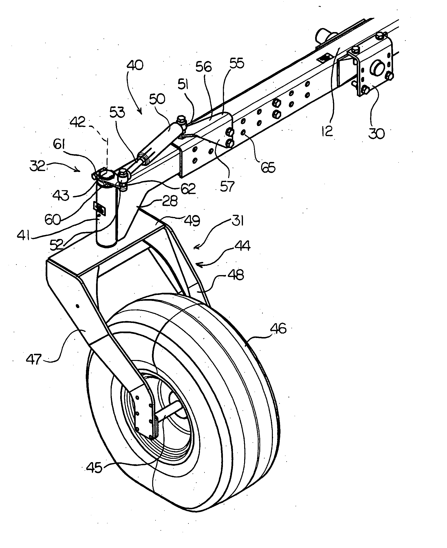
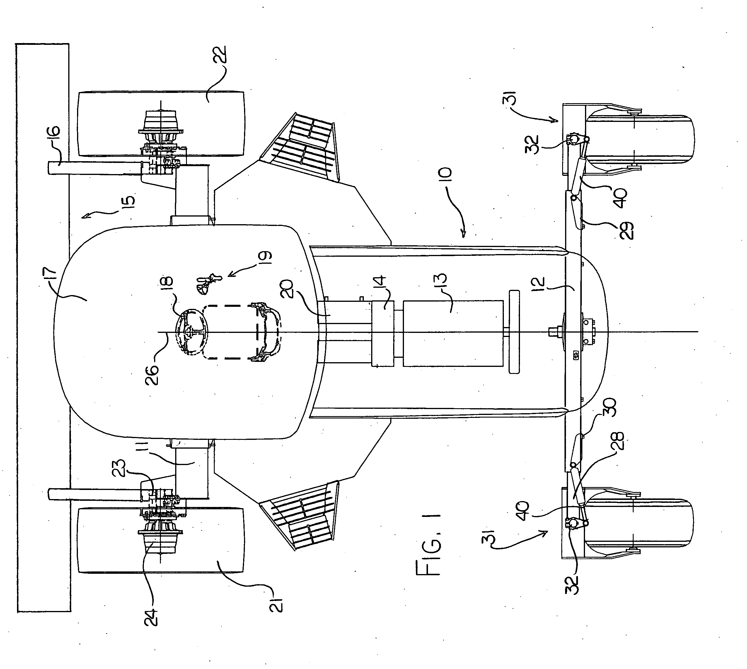
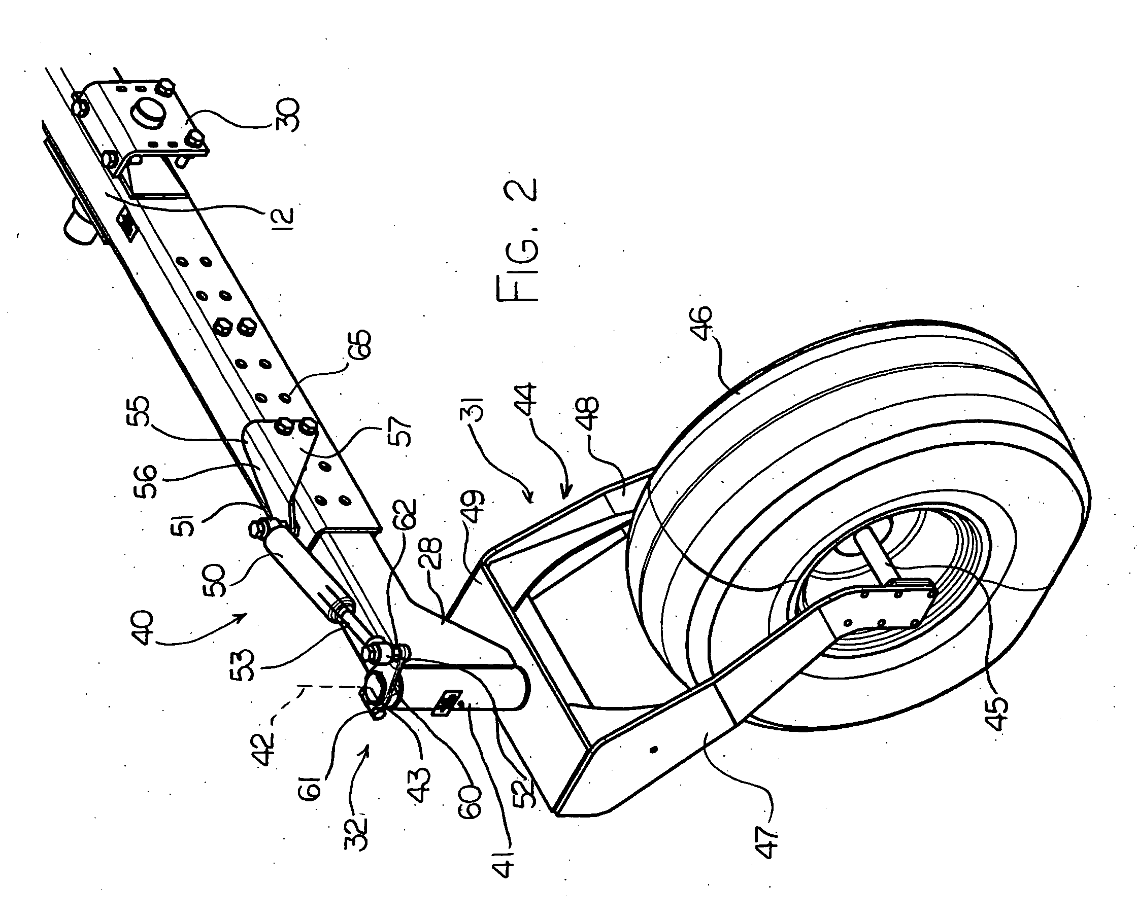
[0061] In FIG. 1 is shown a tractor of the above type which includes a damping system according to the present invention. The tractor is shown schematically but generally includes a frame 10 with a front axle 11 and a rear axle 12. On the frame 10 is mounted a motor 13 driving a gear box and pump assembly schematically indicated at 14 for communicating hydraulic drive fluid to the various components of the tractor for propelling the tractor and for driving an implement 15 mounted on the tractor. In one example, the engine drives a gearbox at the rear of the engine that splits the power to two pump assemblies. One pump assembly has two pumps (one for each wheel) for traction drive & each pump controls one wheel. The other pump assembly has four pumps (two for header drive, one for lift functions and one providing supercharge oil). In the embodiment shown the implement is a header arranged for cutting a standing crop with the header carried on support arms 16 mounted on the tractor at...


PUM


Abstract

A hydrostatic agricultural tractor has front ground wheels mounted on the frame at fixed angles parallel to each other and parallel to a center line of the frame and rear ground wheels mounted on a respective castor, with each of the front ground wheels being driven by a respective drive motor which allows variable speed in both the first and second directions such that steering of the tractor is effected by a differential in speed between the front wheels with the rear wheels following the steering in a castoring action. A pair of damper cylinders is provided each connected between a bracket on a rear axle of the frame and a lever in the castor plane of the castor so as to provide a damping force tending to restrict rotation of the respective second wheel about the respective vertical pivot axis with the damping force at a maximum value when the rear wheels are parallel to the center line in either the forward or reverse directions.

Description

BACKGROUND OF THE INVENTION [0001] Hydrostatically driven tractors used primarily for swathing are commonly used and readily available. The tractor carries at a forward end on suitable sprung supports a header for cutting standing crop with the crop being transported on the header to a suitable discharge location generally centrally of the tractor performing a swath in the field from the cut crop. [0002] Such tractors generally include a pair of front wheels just behind the header which are fixed to the frame of the tractor so that they remain at an angle parallel to each other and parallel to a center line of the tractor. The tractor is supported at the rear end by a pair of castor wheels which are attached to the frame by a conventional castor system at the ends of a rear axle so that the wheels trail behind a vertical pivot mount for the wheels and are free to swivel through 360° around the pivot amount. [0003] The front wheels only are driven and are driven in a manner which all...

Claims


Application Information

Patent Timeline
Patent Type & Authority Applications(United States)
IPC IPC(8): B60B35/10B62D49/00
CPCB60B35/003B60B35/1018B60B35/109Y10T16/196B60Y2200/221B62D49/00B60B2310/305
Inventor DUNN, JAMES THOMASSCHULZ, HENRY JEROMEBERGMAN, LEONARD
Owner MACDON INDS
Why Eureka
Try Eureka