Laser containment structure allowing the use of plastics

a technology of plastic containment and laser, which is applied in the direction of manufacturing tools, mechanical equipment, coatings, etc., can solve the problems of limiting the options of design aesthetics, requiring expensive up-front tooling costs, and relatively expensive sheet metal manufacturing methods

Inactive Publication Date: 2005-06-02
UNIVERSAL LASER SYST
View PDF7 Cites 34 Cited by
  • Summary
  • Abstract
  • Description
  • Claims
  • Application Information

AI Technical Summary

Benefits of technology

[0016] It is a further object of the present invention to provide a laser enclosure for a laser material processing system that provides the required degree of safety while at the same time is able to be manufactured in any desired shape at a reasonable cost.
[0034] The present invention also includes a laser safety enclosure structure with composite structure, having an outer enclosure having an interior surface, the outer enclosure being made of a formable material and including a base member having an upstanding wall which defines an enclosed space for supporting the material object thereon to be processed by a laser beam; and an inner enclosure covering substantially all of the interior surface and defining an interior volume for containing a laser beam, the inner enclosure being composed of at least one layer of a laser beam blocking material, including a first layer, capable of indefinitely withstanding exposure to a laser beam of a predetermined wavelength and power level, the laser beam blocking capability being sufficient to prevent the laser beam incident thereupon from escaping the inner enclosure; and wherein at least the first layer of laser beam blocking material is connected to the interior surface using at least one mechanical fastener.

Problems solved by technology

However, sheet metal has the following drawbacks: 1. sheet metal manufacturing methods may be relatively expensive, especially for mass production; 2. low volume sheet metal manufacturing methods do not allow a wide range of shapes for the enclosures, which limits options for design aesthetics; and 3. stamping methods for sheet metal allow a wider range of shapes, but require expensive up-front tooling costs and are usually reserved for high volume manufacturing.
However, plastics do not meet safety guidelines because they cannot contain a beam indefinitely in the case of direct exposure to the laser beam.
As a result, since such systems are not usually built in large quantities, their enclosures have generally been restricted to square, boxy shapes.

Method used


Image

  • Laser containment structure allowing the use of plastics
  • Laser containment structure allowing the use of plastics
  • Laser containment structure allowing the use of plastics

Examples


Embodiment Construction

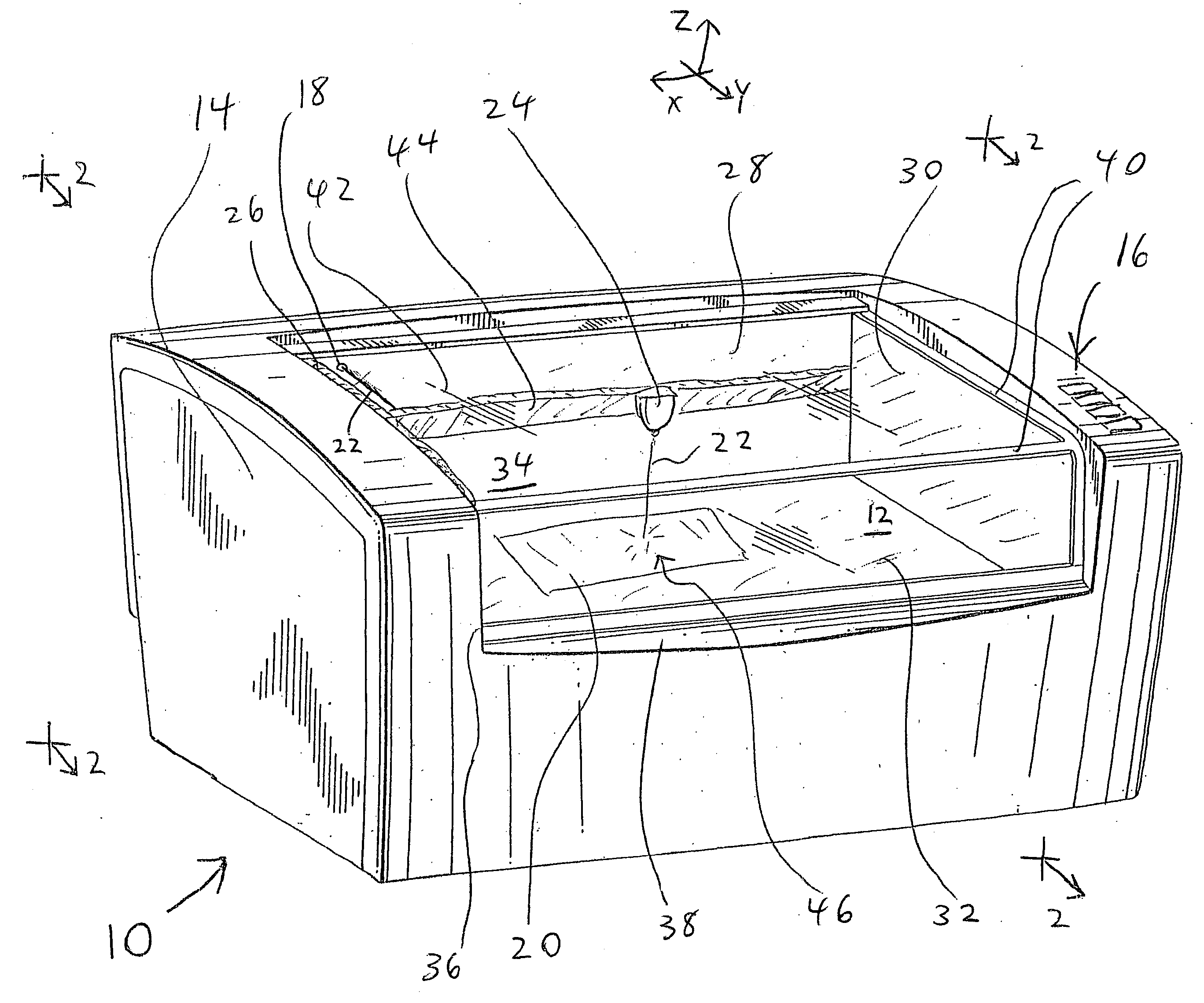
[0045] The present invention is generally directed to a composite structure for a laser safety enclosure in which the exterior material of an outer enclosure is selected for low cost and ease of manufacturing and the ability to be formed into more complex, curved, homogeneous shapes with greater aesthetic appeal and without regard to the ability of the exterior material to block and contain the laser beam. As used in the present application, a material having this ability to be formed into such shapes is termed a formable material, a primary example being plastic.

[0046] The use of this exterior material is combined with the use of an interior material to make an inner enclosure forming an inner laser containment structure having laser beam blocking capability, with the inner material being selected for its ability to block and contain the laser beam. A primary example of a suitable inner material is metal.

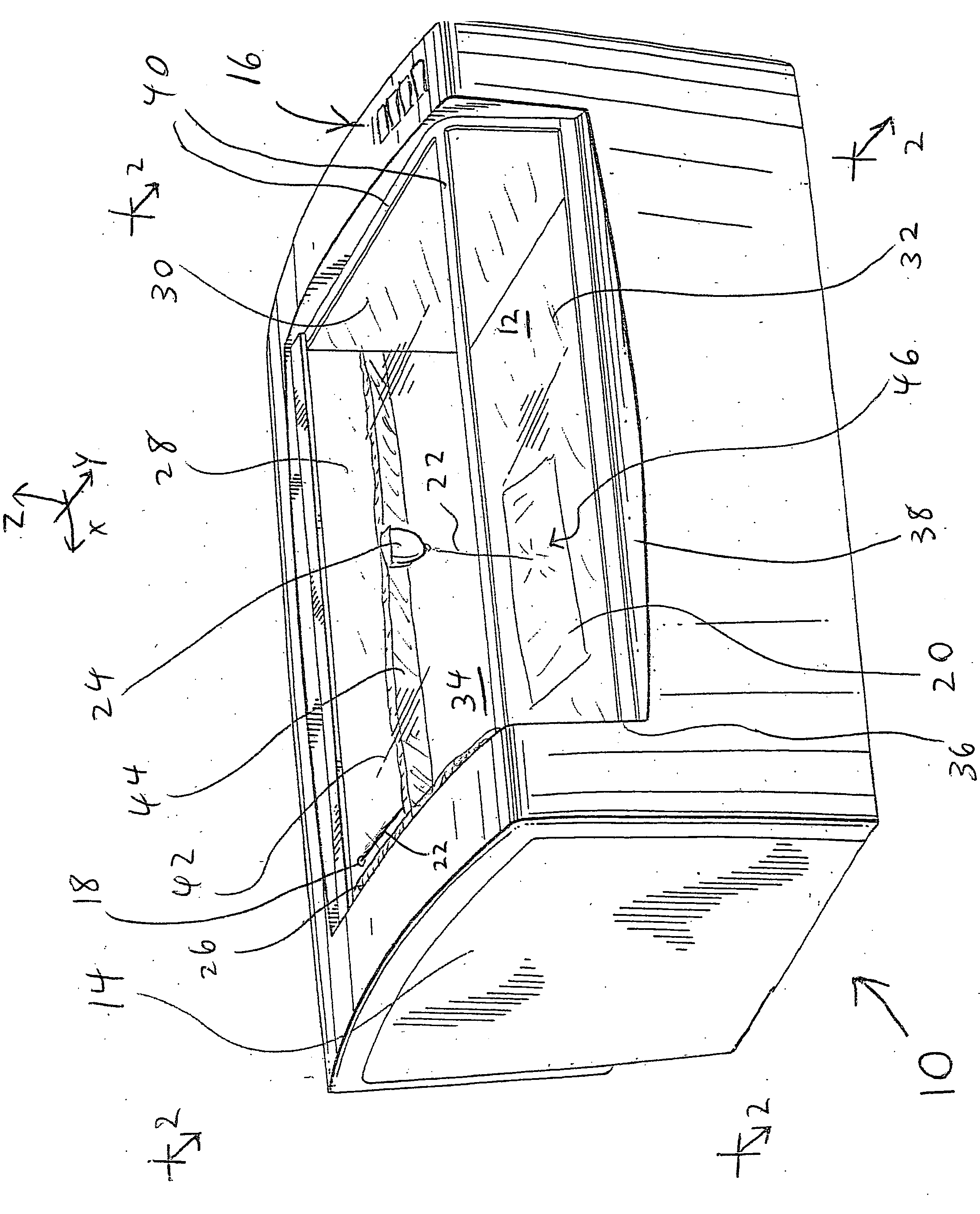
[0047] As shown in FIG. 1, a laser cabinet 10 is illustrated in a top front ...


PUM

PropertyMeasurementUnit
poweraaaaaaaaaa
mechanicalaaaaaaaaaa
shapeaaaaaaaaaa

Abstract

A laser safety enclosure structure has an outer enclosure made of a formable material with a limited ability to withstand exposure to a laser beam and an inner enclosure composed of a laser beam blocking material capable of indefinitely withstanding exposure to a laser beam of a given wavelength and power level so as to prevent such a laser beam incident on the blocking material from escaping the inner enclosure.

Description

CROSS-REFERENCE TO RELATED APPLICATIONS [0001] This application is a continuation-in-part of co-pending U.S. application Ser. No. 10 / 210,121, filed on Jul. 31, 2002; and of co-pending U.S. application Ser. No. 29 / 186,395, filed on Jul. 14, 2003, the disclosures of both applications being incorporated herein by reference in their respective entireties.BACKGROUND OF THE INVENTION [0002] 1. Field of the Invention [0003] This invention relates to laser material processing systems, and in particular to a laser enclosure for safely containing the laser light used in such laser material processing systems. [0004] 2. Description of the Related Art [0005] Material processing systems using high power lasers must be housed in enclosures which contain the laser beam and prevent human exposure to laser radiation in excess of safe limits. This is not only good design practice, but is also required by both federal and state regulations as overseen by the Center for Devices and Radiological Health ...

Claims


Application Information

Patent Timeline
Patent Type & Authority Applications(United States)
IPC IPC(8): B23K26/42B32B15/08C23C30/00F16P1/06H01S3/00
CPCB23K26/427B32B15/08H01S3/00F16P1/06C23C30/00B23K26/706
Inventor SUKHMAN, YEFIM P.RISSER, CHRISTIAN J.GORHAM, EDWIN W.NOTO, STEFANO J.WORTH, CORY W.AITCHISON, DAVID J.
Owner UNIVERSAL LASER SYST
Why Eureka
Try Eureka