Encoder structure

a technology of encoder and encoder body, which is applied in the direction of brake system, instruments, transportation and packaging, etc., can solve the problems of accumulating deposits of iron particles, and achieve the effect of ensuring durability and reliability of encoder, eliminating deposits, and reducing surface damag

Inactive Publication Date: 2005-06-02
SUBARU CORP
View PDF2 Cites 5 Cited by
  • Summary
  • Abstract
  • Description
  • Claims
  • Application Information

AI Technical Summary

Benefits of technology

[0007] For resolving the problems of existing encoder structures, the present invention has an object to provide an encoder structure that ensures durability and reliability of an encoder by eliminating deposits and reducing damages to the surface of the encoder and a sensor head unit.

Problems solved by technology

Further, deposits of the iron particles tend to be accumulated after a prolonged use.

Method used


Image

  • Encoder structure
  • Encoder structure
  • Encoder structure

Examples


first embodiment

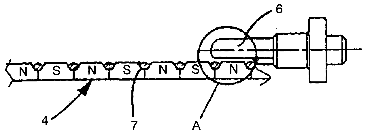
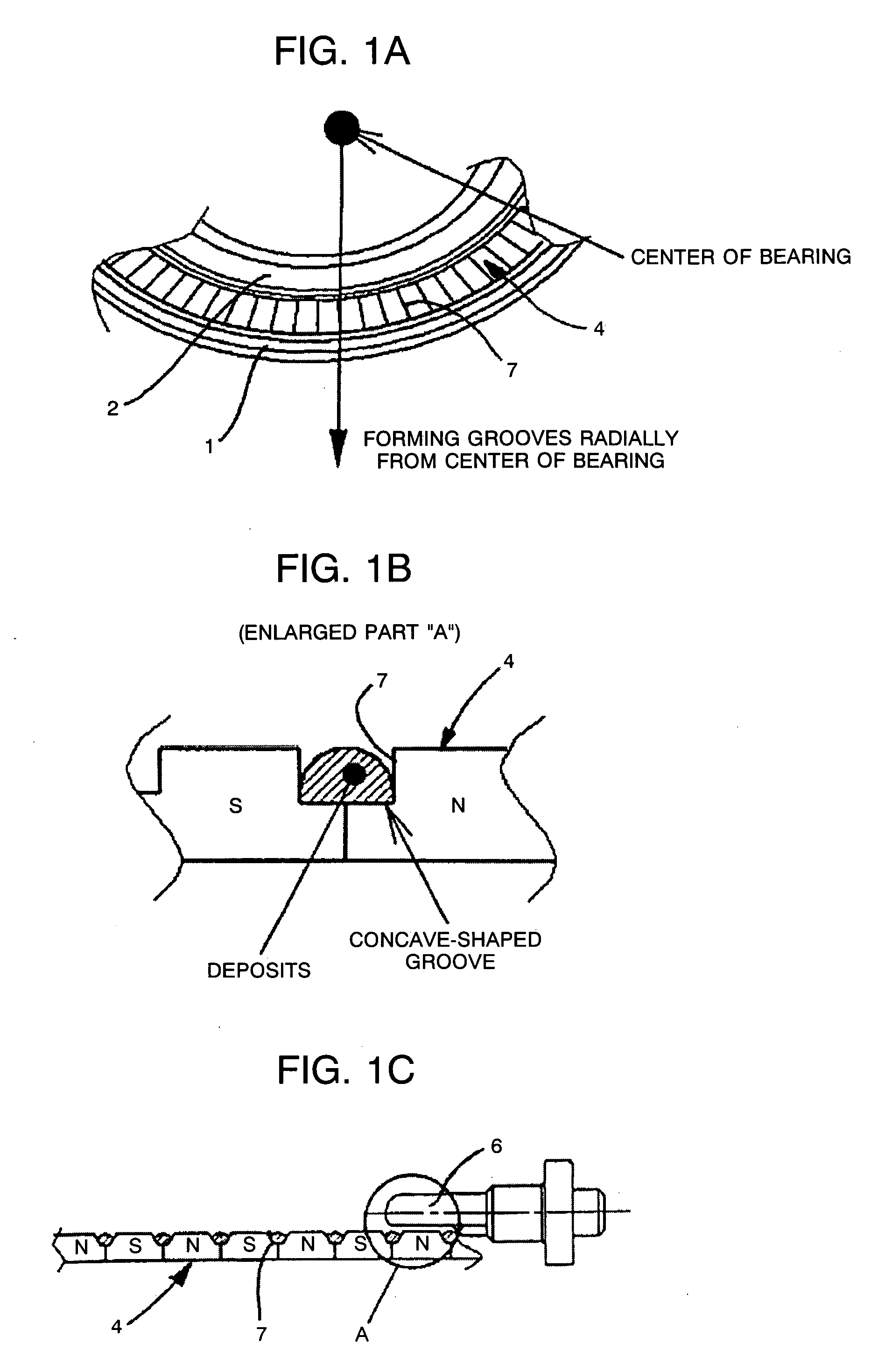
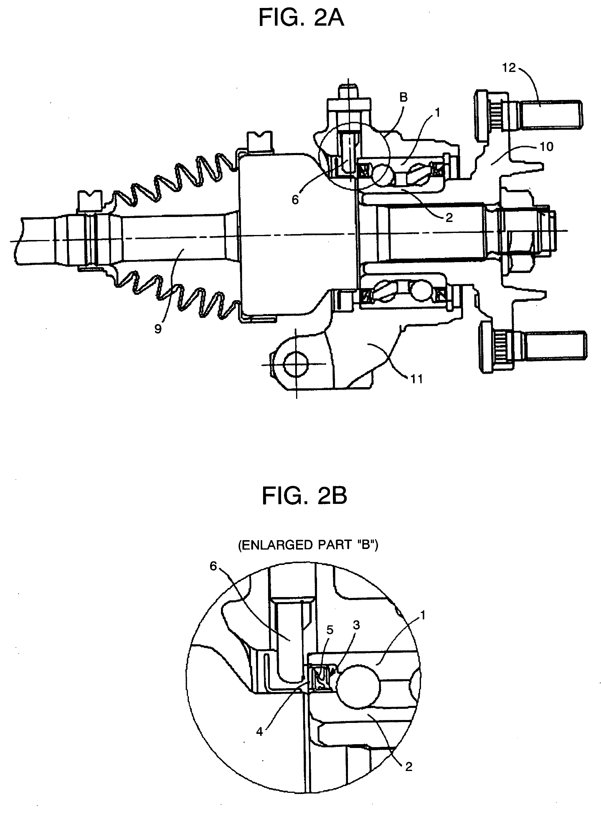
[0020] A description will be now given of the first embodiment of the present invention. As Shown in FIG. 2, an encoder 3 according to the present invention is adopted to a sealing device for a bearing of a shaft. However, the adoption of the encoder 3 is not limited to the shaft, and is allowed to other parts where hermetically sealing is necessary and rotational and irrotational parts are close to each other. As shown in FIG. 2A, a wheel hub 10 is supported in an axial direction against a wheel housing 11, that is, the irrotational part fixed to a vehicle body, by the bearing comprising an outer ring 1 and an inner ring 2 together holding balls therebetween. One end of a drive shaft 9 is combined with an inner side of the wheel hub 10 by a spline connection. A reference number “12” indicates a hub nut fixed to the wheel hub 10 and locks a wheel disk.

[0021] The encoder 3 according to the present invention is positioned between one end of the outer ring 1 and the corresponding end ...

second embodiment

[0024]FIG. 4 is the enlarged cross-sectional diagram showing the magnetic ring unit 4 regarding the second embodiment of the encoder structure according to the present invention. In the present embodiment, the groove unit 7 is formed so that the cross section of the groove unit 7 is shaped like a horseshoe. Since the groove unit 7 has a circular configuration especially at its bottom corner by forming the cross-sectional shape of the groove unit 7 to a horseshoe shape, the deposits are hardly accumulated at the bottom corner. Additionally, the capacity of the groove unit 7 for the deposits can be determined by selecting the cross-sectional shape of the groove unit 7 from a V shape, a trapezoid, a half-arc shape or the like. Meanwhile, the durability of each magnetic ring unit 4 is ensured according to the shape-related characteristics based on the relation between the strength and durability of the magnetic ring unit 4 regarding formation of the groove unit 7.

third embodiment

[0025]FIG. 5 is the enlarged cross-sectional diagram showing the magnetic ring unit 4 regarding the third embodiment of the encoder structure according to the present invention. In the present embodiment, a circumferentially extending groove 8 is formed adjacently to the bottom of the groove unit 7 to have a key-shaped groove unit 13. Normally, the groove unit 7 is supposed to be formed so that the surface area of the magnetic ring unit 4 becomes an area “b”. However, formation of the groove 8 secures the relatively large surface area “a” of the magnetic ring unit 4 and the large capacity for the deposits at the same time (a>b). According to the third embodiment, the magnetic ring unit 4 can secure the relatively large surface area to acquire a high magnetic characteristic in spite of having the groove unit 7 and the groove 8. In addition, the gutter-like effect caused by the centrifugal force of a rotating wheel and a water-spitting-out effect caused by the waterwheel-like effect t...


PUM


Abstract

An encoder structure includes a sensor head unit 6 installed in an irrotational part, a rotative magnetic ring unit 4 that is positioned close to the sensor head unit 6 and has a north pole and a south pole arranged alternately on a circumference thereof, and a groove unit 7 formed in at least one of spaces between the north pole and the south pole located on a surface of the magnetic ring unit 4. Thus, deposits such as iron particles are easily drained away with muddy water because a part where the iron particles tend to be accumulated along a magnetic flux functions as a groove-like path. Additionally, accumulated iron particles remain inside the groove unit 7 that is concave shaped. Accordingly, prevention of damage to the sensor head unit 6 is achieved.

Description

BACKGROUND OF THE INVENTION [0001] 1. Field of the Invention [0002] The present invention relates to an encoder structure that is positioned close to a sensor head unit installed in an irrotational part with a rotative magnetic ring unit of which circumference has north and south poles arranged alternately. The present invention is applied particularly to an encoder that is utilized as a sensor installed in a wheel speed detecting device of an automobile ABS (Anti Lock Brake System) and functions as a sealing device for a shaft bearing part. [0003] 2. Description of the Related Art [0004] There has been widely used a device for detecting a magnetic force alteration associated with relative rotation of an encoder and a sensor head unit, as a wheel speed detecting device of an automobile ABS. The encoder or a magnetic material is attached to a rotational part such as a drive shaft and a bearing and is positioned close to the sensor head unit installed in their rotational part such as ...

Claims


Application Information

Patent Timeline
Patent Type & Authority Applications(United States)
IPC IPC(8): B60T8/171F16C33/58F16C33/78F16C41/00G01D3/08G01D5/245G01P3/487
CPCF16C33/667F16C33/78F16C2326/02G01D5/24438G01P3/487F16C41/007F16C19/184G01D2205/80
Inventor MATSUMOTO, YASUAKI
Owner SUBARU CORP
Why Eureka
Try Eureka