Element board for printhead, printhead and printhead control method

Inactive Publication Date: 2005-06-02
CANON KK
View PDF9 Cites 25 Cited by
  • Summary
  • Abstract
  • Description
  • Claims
  • Application Information

AI Technical Summary

Benefits of technology

[0014] It is an object of the present invention to provide an element bo

Problems solved by technology

An increase in the number of input terminals leads to a decrease in connection reliability and an increase in chip area, raising the chip cost.
Sin

Method used


Image

  • Element board for printhead, printhead and printhead control method
  • Element board for printhead, printhead and printhead control method
  • Element board for printhead, printhead and printhead control method

Examples


Example

First Embodiment

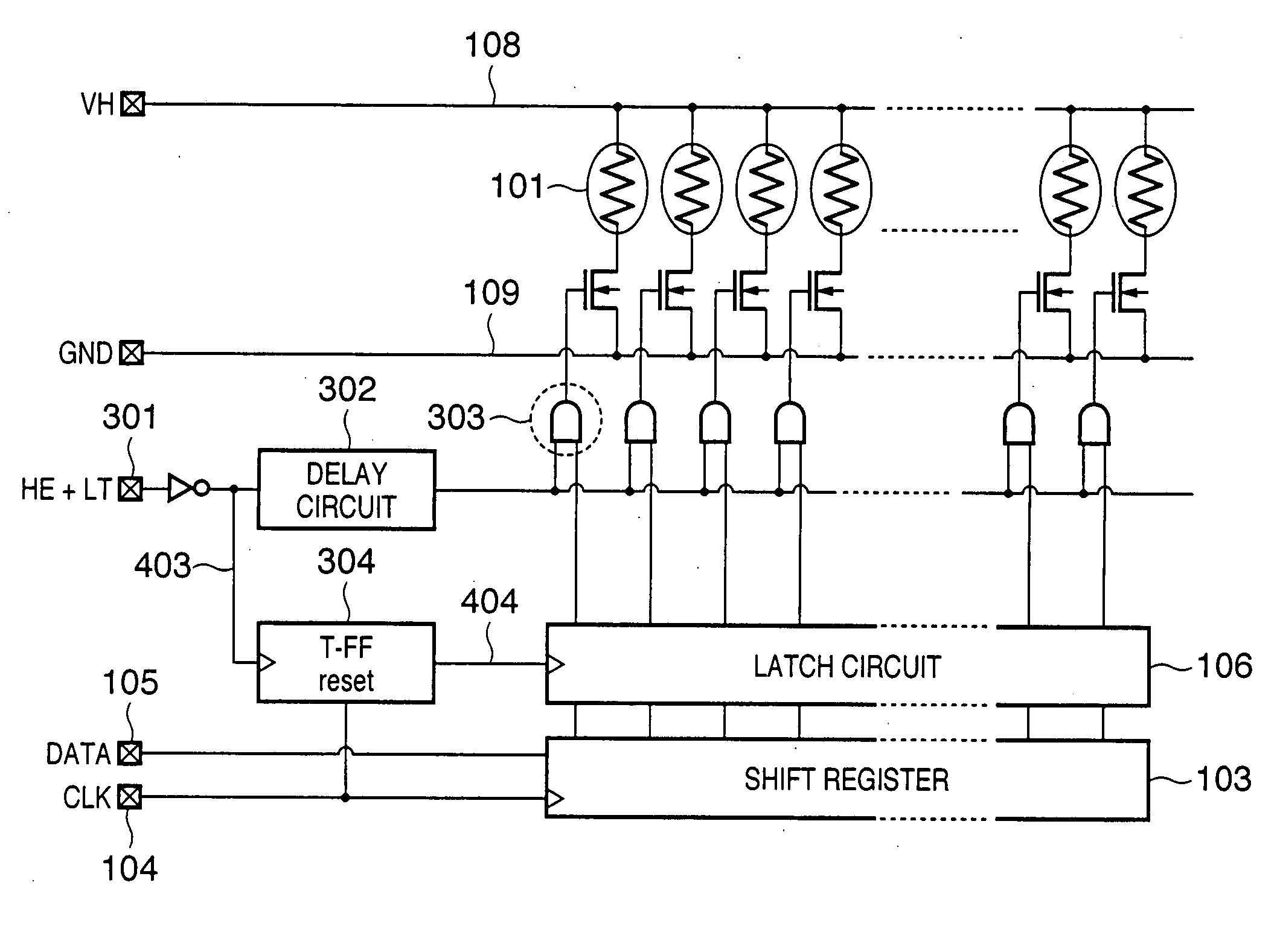
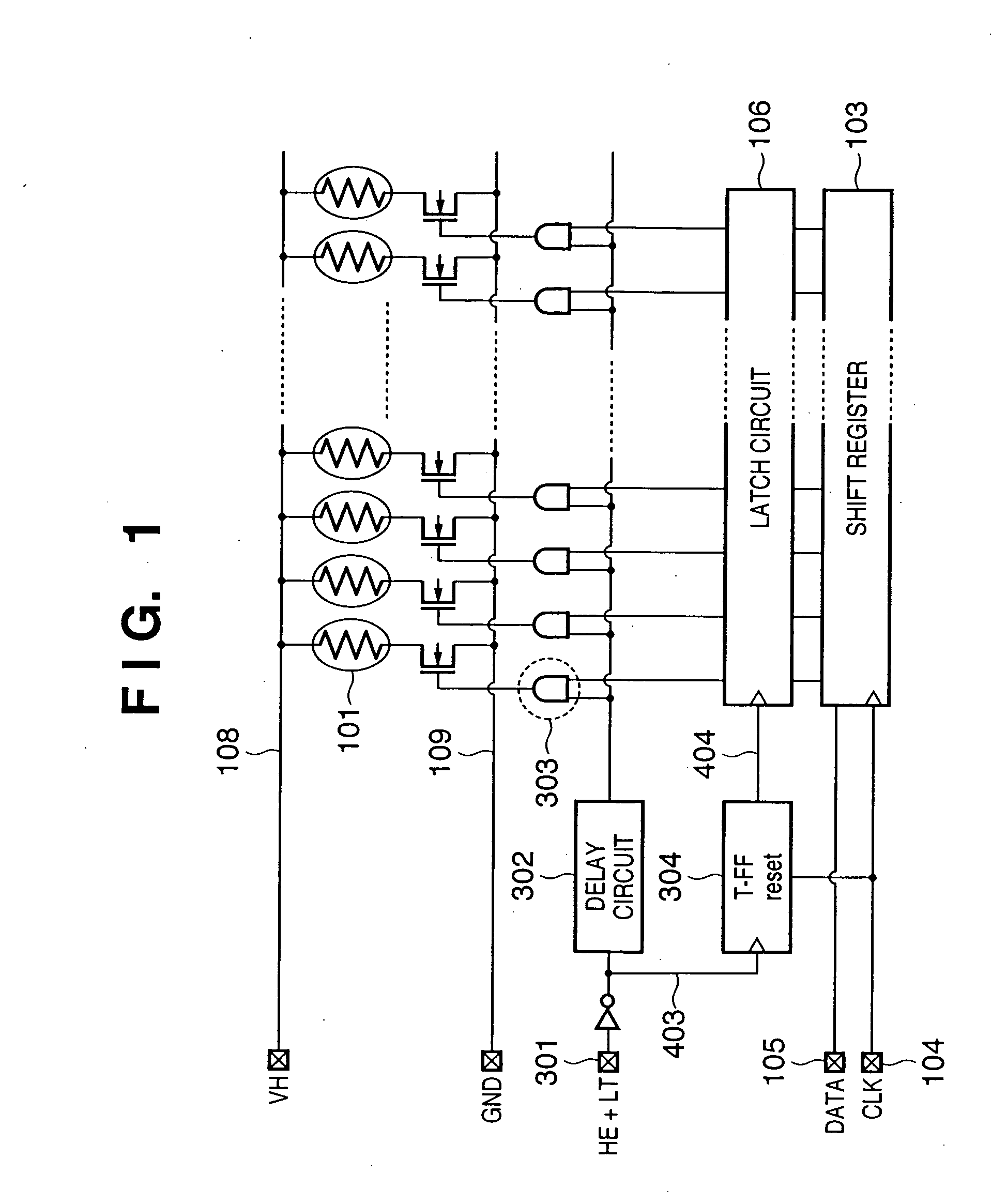
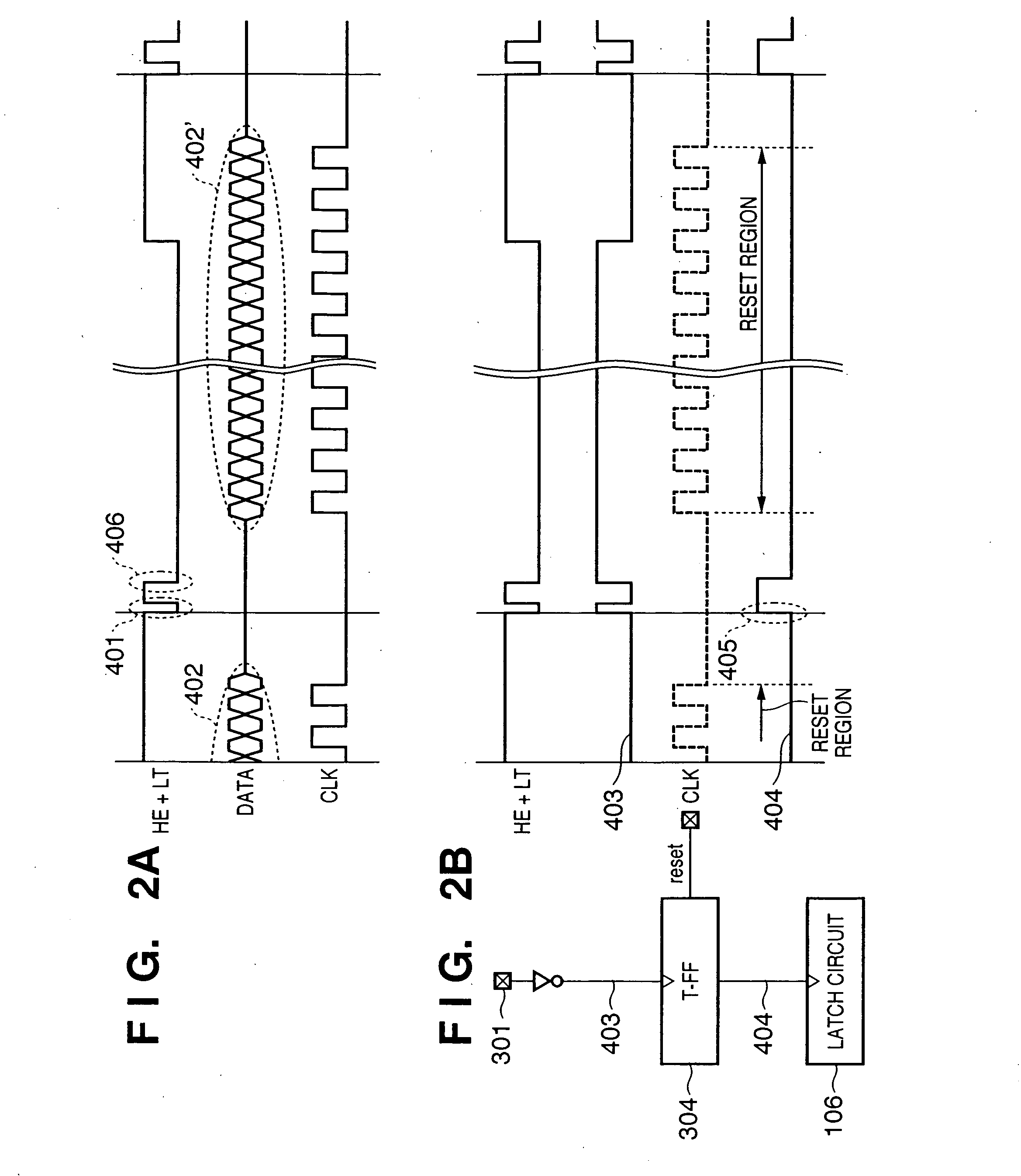
[0076]FIG. 1 is a block diagram showing the circuit configuration of the first embodiment of an inkjet printhead according to the present invention. FIGS. 2A and 2B are timing charts showing the states of signals in the circuit of FIG. 1.

[0077] Periods and timings of the each signal are as follows. The frequency of the clock signal ranges from 6 to 12 MHz, the ejection frequency (driving frequency) is about 15 kHz, and hence the period of the heat signal is about 4 μsec. The period between falling edge and rising edge of the pre-pulse 401 ranges from 0.2 to 0.6 μsec, the period between falling edge and rising edge of the main pulse 406 ranges from 0.6 to 1.2 μsec, and the rest period between the two pulses ranges from 0.2 to 1.0 μsec. The widths of the pulses change in accordance with temperature rise of the printhead.

[0078] In FIG. 1, reference numeral 301 denotes an input terminal which receives an HE+LT signal serving as both a heat enable signal and latch sign...

Example

Second Embodiment

[0091] The second embodiment of the circuit configuration of an inkjet printhead according to the present invention will be described. In the following description, a description of the same parts as those in the first embodiment will be omitted, and characteristic features of the second embodiment will be mainly explained.

[0092] In the first embodiment, a double-pulse heat enable signal is input as the HE+LT signal, and the leading edge of a pre-pulse signal is used as a trigger to the latch circuit. In the second embodiment, a single-pulse heat enable signal is input as the HE+LT signal, and the leading edge of a pulse signal is used as a trigger to the latch circuit.

[0093]FIG. 4A is a timing chart showing the states of signals according to the second embodiment.

[0094] In FIG. 4A, the timing of a pulse leading edge 601 of an LT+HE signal is set between DATA signals 602 and 603 while ensuring sufficient time intervals from both the DATA signals 602 and 603.

[00...


PUM


Abstract

In a printhead having a plurality of printing elements, a shift register which serially receives printing data corresponding to the number of printing elements, a latch which latches the printing data input to the shift register, and a driving circuit which selectively drives the printing elements in accordance with the printing data latched by the latch and a signal representing a driving period, the latch state of the latch is controlled by the signal representing the driving period. The signal representing the driving period and a signal for controlling the latch state of the latch are commonly used to decrease the number of input terminals of the printhead.

Description

FIELD OF THE INVENTION [0001] The present invention relates to an element board for a printhead, a printhead and printhead control method and, more particularly, to a printhead which has a plurality of printing elements and prints by driving the printing elements in accordance with serially input printing data, and a printhead control method. [0002] The present invention can be applied to a general printing apparatus which prints by using such a printhead, and also to an apparatus (e.g., a copying machine, facsimile apparatus, or wordprocessor) and an industrial printing apparatus compositively combined with various processing apparatuses. BACKGROUND OF THE INVENTION [0003] A printing apparatus which prints information such as a desired character or image on a sheet-like printing medium such as a paper sheet or film is widely used as an information output apparatus in a wordprocessor, personal computer, facsimile apparatus, and the like. [0004] Various methods are known as printing ...

Claims


Application Information

Patent Timeline
IPC IPC(8): B41J2/05B41J2/01B41J2/235
CPCB41J2/04541B41J2/0458B41J2/0455B41J2/04501B41J2/01B41J2/05B41J2/235
Inventor KASAI, RYO
Owner CANON KK
Why Eureka
Try Eureka