Vascular exclusion catheter

a vascular exclusion and catheter technology, applied in the field of vascular exclusion catheters, can solve the problems of loss of fluid such as blood, invading the general surgical environment with fluid, and many people's perception of trauma, and achieve the effect of convenient fluid flow and simple us

Inactive Publication Date: 2005-06-02
NGUYEN ERIC +5
View PDF5 Cites 91 Cited by
  • Summary
  • Abstract
  • Description
  • Claims
  • Application Information

AI Technical Summary

Problems solved by technology

This not only results in a loss of fluid such as blood, but also invades the general surgical environment with the fluid.
Particularly in the case of blood vessels, this is undesirable as an uninterrupted flow of blood is necessary to maintain the tissues of the body.
While the partial occluding clamp is relatively simple to use, it is perceived by many to be very traumatic.
Its use has been reported to cause secondary complications such as the fracturing of plague and resultant Transient Ischemic Attack or Cerebral Vascular Accident, with both local and global consequences.
The partial occluding clamp also consumes much of the procedural area not only with its jaws on the aorta, but also with its clamp handles in the surgical field.

Method used


Image

  • Vascular exclusion catheter
  • Vascular exclusion catheter
  • Vascular exclusion catheter

Examples


Embodiment Construction

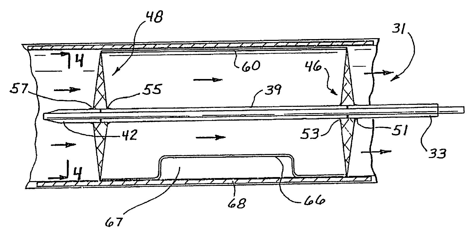
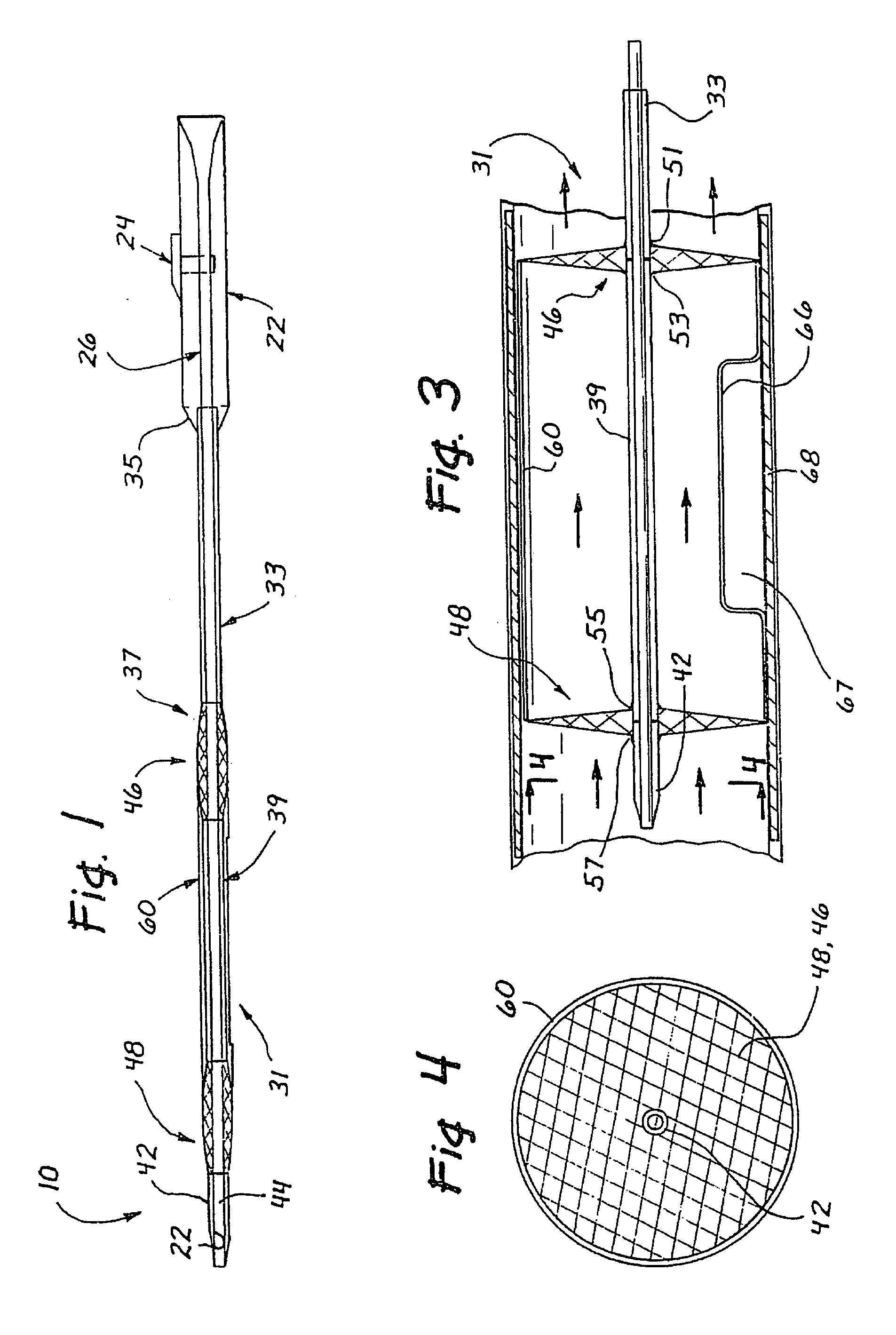
[0040] An exclusion catheter apparatus is illustrated in FIG. 1 and designated generally by the reference numeral 10. This particular apparatus 10 is adapted to exclude a segment of a body conduit while facilitating flow through the remainder of the conduit. The apparatus 10 comprises a handle assembly 20 with a hand piece 22 and an axially movable thumb slide 24. The thumb slide 24 is coupled to an inner elongate member 26 of a tube assembly 31. In the preferred embodiment, the inner elongate member 26 comprises a tube with a hollow core or lumen 27. Alternatively, the inner elongate member 26 may have a solid core and, thus, comprise a wire, for example.

[0041] The handle assembly 20 is coupled to the tube assembly 31, which in this embodiment comprises a first proximal outer tube 33 coupled to a distal portion 35 of the handle assembly 20. The inner elongate member 26 is disposed within the proximal outer tube 33, and extends distally outwardly from a distal tip 37 of the outer t...


PUM


Abstract

A fluid controlled device is adapted for disposition in a body conduit where it controls the flow of body fluids within the conduit. A sleeve is provided with a wall of separation having a first surface which defines a flow passage facilitating the flow of body fluids, and a second surface which defines an exclusion chamber sealed from the flow passage. Various dilators have properties for moving the seal between a low-profile state facilitating insertion of the device, any high-profile state defining the flow passage and exclusion chamber. The dilator may be skeletal, inflatable, and / or porous. An associated method includes the step of dilating a dilation assembly to move a wall from a low profile, insertible state, to a high-profile wherein the wall defines a flow passage and an exclusion cavity.

Description

[0001] This is a non-provisional application claiming the benefits of Patent Convention Treaty Application Serial No. PCT / US02 / 28830 filed on Sep. 10, 2002 and entitled “Vascular Exclusion Catheter”; and U.S. Provisional Application Ser. No. 60 / 339,901 filed on Oct. 30, 2001 and entitled “Vascular Exclusion Catheter”, both of which are fully incorporated herein by reference.BACKGROUND OF THE INVENTION [0002] 1. Field of the Invention [0003] This invention relates generally to apparatus and methods for at least partially occluding flow within a body conduit. [0004] 2. Discussion of the Relevant Art [0005] Body conduits commonly provide for a flow of fluid from one location in the body to another location in the body. Typical of these fluid conduits are arteries and veins of the vascular system which provide a flow of blood between the heart and the organs of the body. When a particular procedure requires that the vessel be accessed, the flow of blood can be expected to exit the condu...

Claims


Application Information

Patent Timeline
Patent Type & Authority Applications(United States)
IPC IPC(8): A61B17/12A61M25/10A61M29/00A61M29/02
CPCA61B17/12022A61B17/12036A61B17/12045A61B17/12109A61B17/12136A61M2025/1081A61B2017/12127A61M25/1002A61M25/1011A61M29/02A61B17/12172
Inventor NGUYEN, ERICBRUSTAD, JOHN RPETRIME, MATTHEW NJOHNSON, GARY MCOX, JOHN AHART, CHARLES C
Owner NGUYEN ERIC
Why Eureka
Try Eureka