Apparatus and method for performing speculative reads from a scan control unit using FIFO buffer units

a technology of speculative reads and buffer units, applied in the field of emulators, can solve the problems of increasing the speed of the test clock, the number of times, and the registers in the scan control unit can become a limiting factor of the performance of the testing procedure,

Active Publication Date: 2005-06-02
TEXAS INSTR INC
View PDF16 Cites 19 Cited by
  • Summary
  • Abstract
  • Description
  • Claims
  • Application Information

AI Technical Summary

Benefits of technology

[0016] The aforementioned features are accomplished, according to the present invention, by providing a put buffer unit in the scan control unit. The put buffer unit receives data signal groups from the test and debug processing unit and transfers these groups through the scan control unit to the target processing unit. The put buffer unit transfers the data signal groups to the target processing unit, but retains a copy of the data signal groups. If the transfer to the target processing unit fails, the put buffer unit can resend the data signal group until a successful transfer is achieved. The put buffer unit is synchronized with the target processing unit clock. In addition, the put buffer unit provides signals indicative of the remaining storage space in the unit to prevent attempts by the test and debug unit to store data signal groups when insufficient storage space is available.

Problems solved by technology

In a high performance scan controller, the number of times the test and debug unit must load the registers in the scan control unit can become a limiting factor of the performance of the testing procedure.
This problem is compounded by the increasing speed of the test clock, which is the speed at which data is serialized and sent to the target processor.
If the target processor is also returning information, then data transfers will be consuming 80% of the bus bandwidth.
Widening the data path requires additional pins on the scan controller device, the debug unit and the memory, and may not always be possible.
Reducing the access time of the scan control unit or memory might be possible, but is limited by the particular implementation of both.
The transaction retries impact the performance of the test and debug configuration and, in the situation involving large data transfers with many retries, can result in a significant degradation of the configuration performance.
When dealing with large, variable amounts of data, registers become impractical.
The problem with using a FIFO is the data gets “consumed” when it is read, it can only be read once.
They can fail for a variety of reasons, such as the target processing unit has inhibited emulator access during critical sections of code execution, the test and debug system can have insufficient priority to access memory, or the memory system may simply be busy.
If a scan control unit is using a FIFO unit for data storage, these failures can result in loss of data or invalid data values being returned.

Method used


Image

  • Apparatus and method for performing speculative reads from a scan control unit using FIFO buffer units
  • Apparatus and method for performing speculative reads from a scan control unit using FIFO buffer units
  • Apparatus and method for performing speculative reads from a scan control unit using FIFO buffer units

Examples


Embodiment Construction

1. Detailed Description of the Figures

[0024]FIGS. 1, 2, 3, and 4 have been described with respect to the related art.

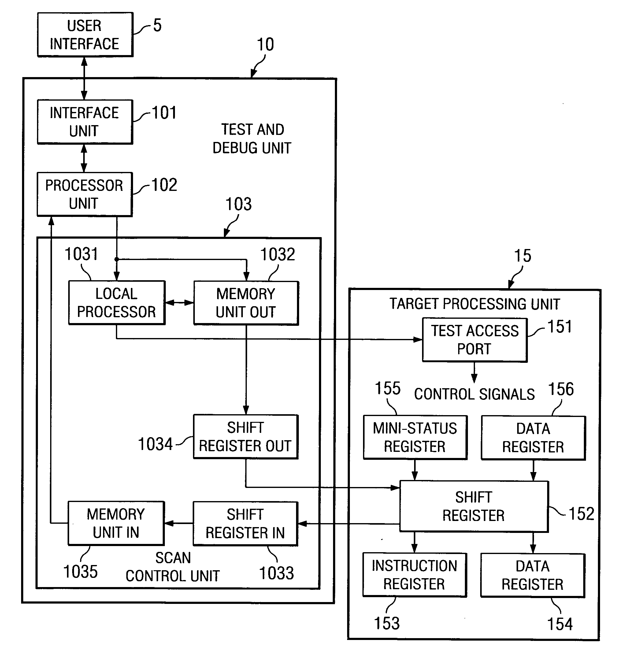
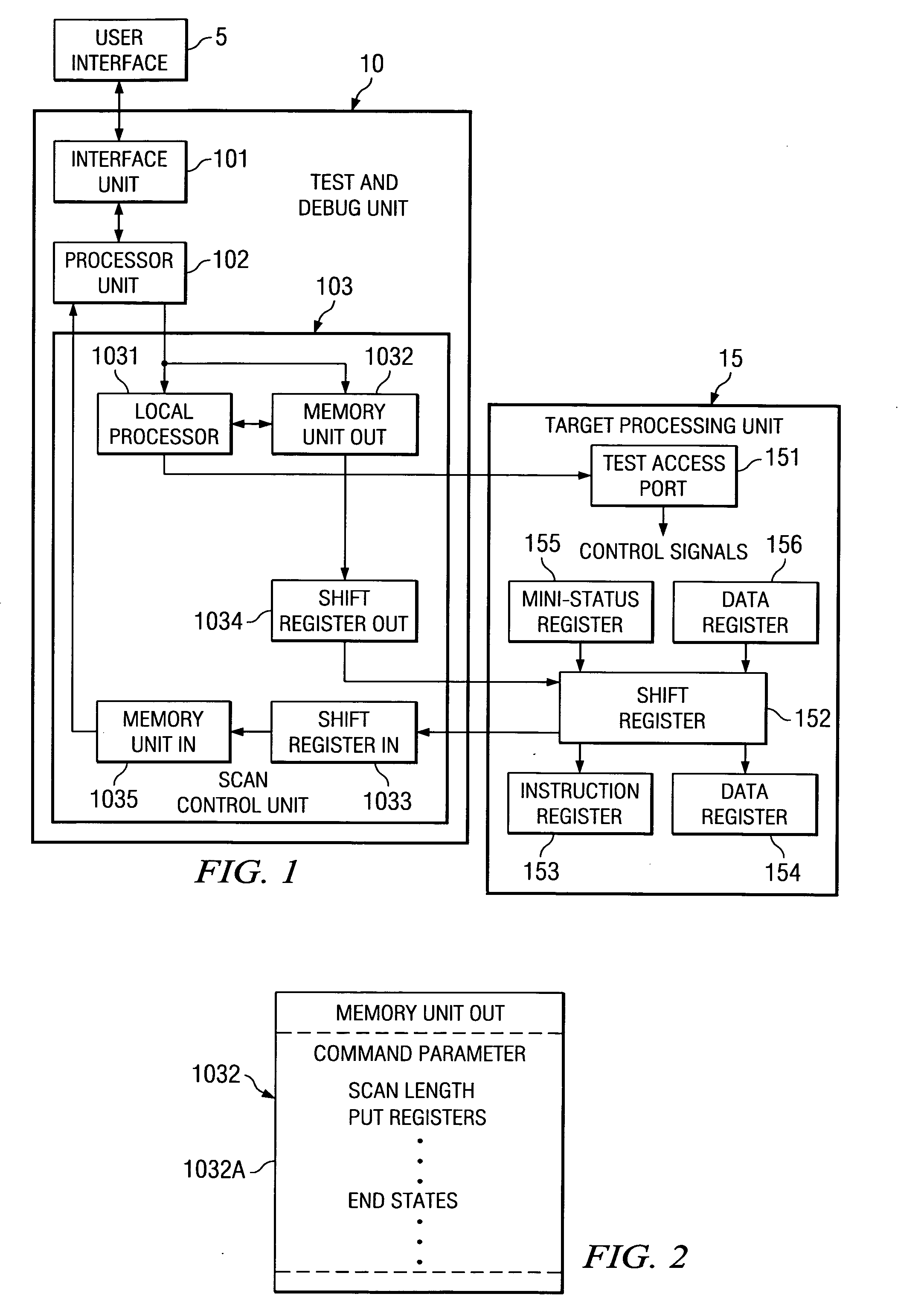
[0025] Referring next to FIG. 5A, the structure of the memory unit out 1032 according to present invention is shown. The memory unit out 1032 includes command parameter storage locations 1032A. The command parameter storage locations 1032A are storage location scan lengths and end states, states that must be communicated to the target processing unit. In storage locations 1032B, the fixed length signal groups to be transferred to the target processing unit. In the storage locations 1032C, the signal groups are stored that have a variable length. In the preferred embodiment, these storage locations are implemented by a FIFO (first-in first-out) memory unit.

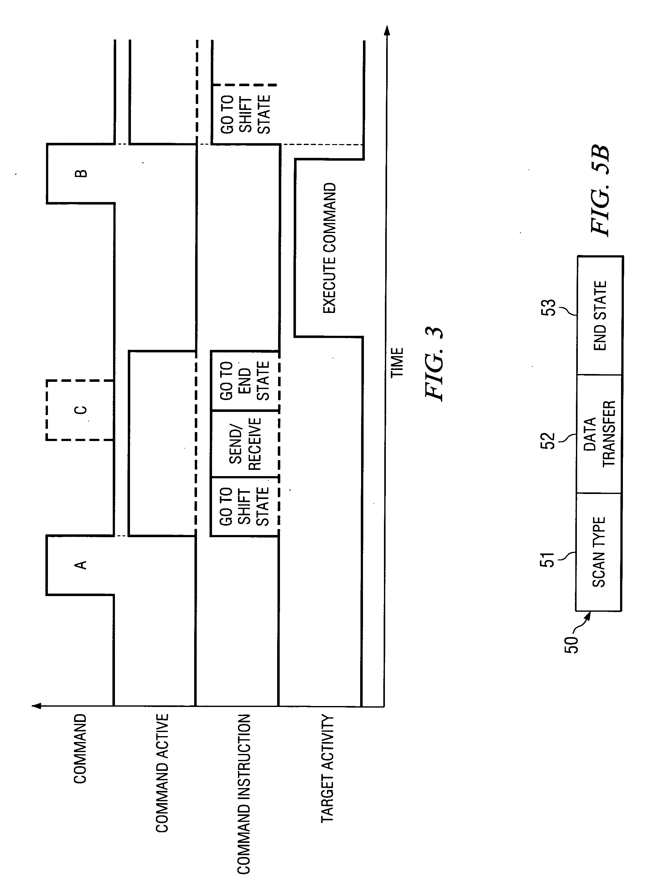
[0026] Referring to FIG. 5B, the structure of a command applied to the scan control unit 103 from the test and debug processing unit is shown. The command 50 includes, for purposes of this discussion, three parame...


PUM


Abstract

In a JTAG test and debug environment, the signal groups may have a variable length, a fixed length of a combination of both fixed and variable signal groups to be transferred to the target processor. To implement the three types of data transfers, the storage unit associated with the scan control unit includes two types of storage locations, fixed signal length storage locations and variable length storage locations. The software can select the mode of data transfer and this selection is provided to the scan controller by a command.

Description

[0001] This application claims priority under 35 USC §119(e)(1) of Provisional Application No. 60 / 517,536 (TI-37248P) filed Nov. 05, 2003.1. FIELD OF THE INVENTION [0002] This invention relates generally to the use of emulation units to perform test and debugging operations on a digital signal processor target system and, more particularly, to providing a method for optimizing JTAG (Joint Test Action Group) transfers between a test and debug unit and target processor. The present invention improves the performance of the test and debug unit in boundary scans. 2. BACKGROUND OF THE INVENTION [0003] In the past, test and debug procedures on digital signal processors was done using a scan control unit that converts parallel information from a test and debug unit into a serial data stream. The data values to be scanned out needed to be loaded each time a scan was executed, unless all of the data values were identical. [0004] In a high performance scan controller, the number of times the ...

Claims


Application Information

Patent Timeline
Patent Type & Authority Applications(United States)
IPC IPC(8): G06F11/00G06F11/267
CPCG06F11/2236
Inventor LARSON, LEE A.HOAR, HENRY R.
Owner TEXAS INSTR INC
Why Eureka
Try Eureka