

Electronic device and antenna apparatus
a technology of antenna and antenna body, which is applied in the direction of loop antennas with ferromagnetic cores, instruments, etc., can solve the problems of high-grade appearance, inferior texture and weight of wristwatch cases of resins, and degrade so as to achieve the effect of not degrading the reception sensitivity of antennas
- Summary
- Abstract
- Description
- Claims
- Application Information
AI Technical Summary
Benefits of technology
Problems solved by technology
Method used
Image

Examples
first embodiment
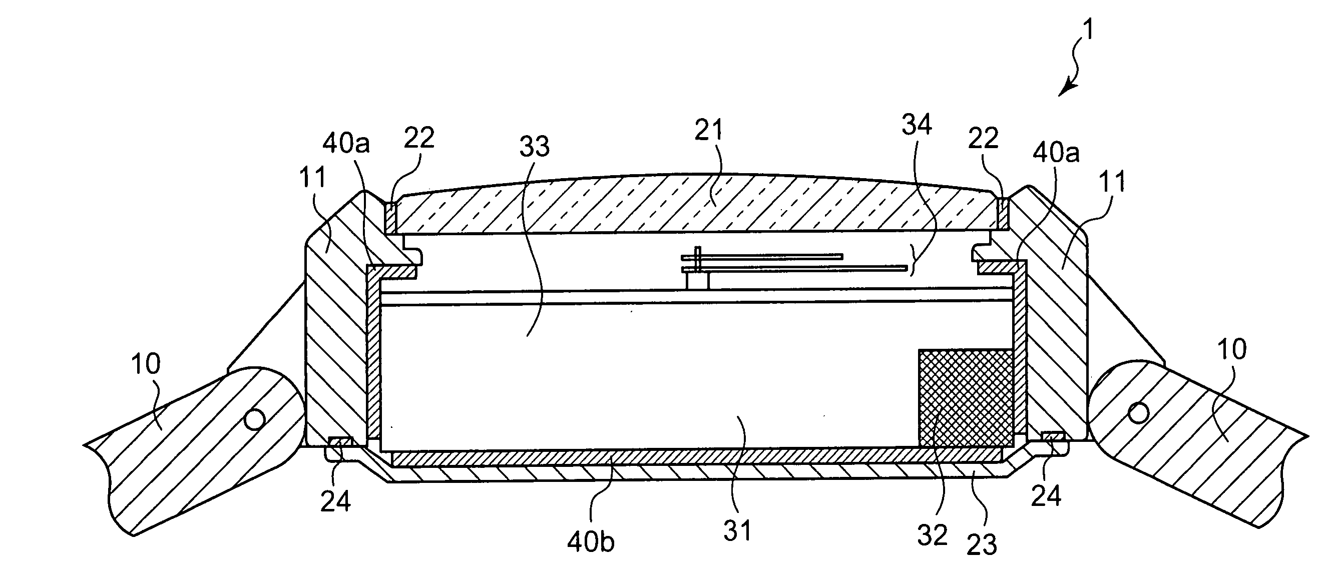
[0045]FIG. 1 is a schematic cross-sectional view of a wristwatch 1 according to the first embodiment. The wristwatch 1 has a watch case 11 as an armoring component and a back cover 23 as an armoring component. The watch case 11 and the back cover 23 constitute the casing of an electronic device. A watch module 31 is housed in the watch case 11 of the wristwatch 1, and an antenna 32 which receives standard radio waves is retained in the watch module 31. Bands 10, 10 for mounting an electronic device to an arm are attached to the wristwatch 1 in the directions of 12 o'clock and 6 o'clock of the watch case 11.
[0046] The antenna 32 is a bar antenna, and includes a rod-shaped core formed of a magnetic material, such as amorphous magnetic or ferrite, which has a high specific magnetic permeability with and a low electric conductivity, and a coil obtained by winding a conductive wire of copper or so around the core. When the antenna 32 is placed in a magnetic field generated by the standa...
second embodiment
[0055] The second embodiment will be described below.
[0056] To avoid the redundant description, like or same reference numerals are given to those components of the second embodiment which are the same as the corresponding components of the first embodiment.
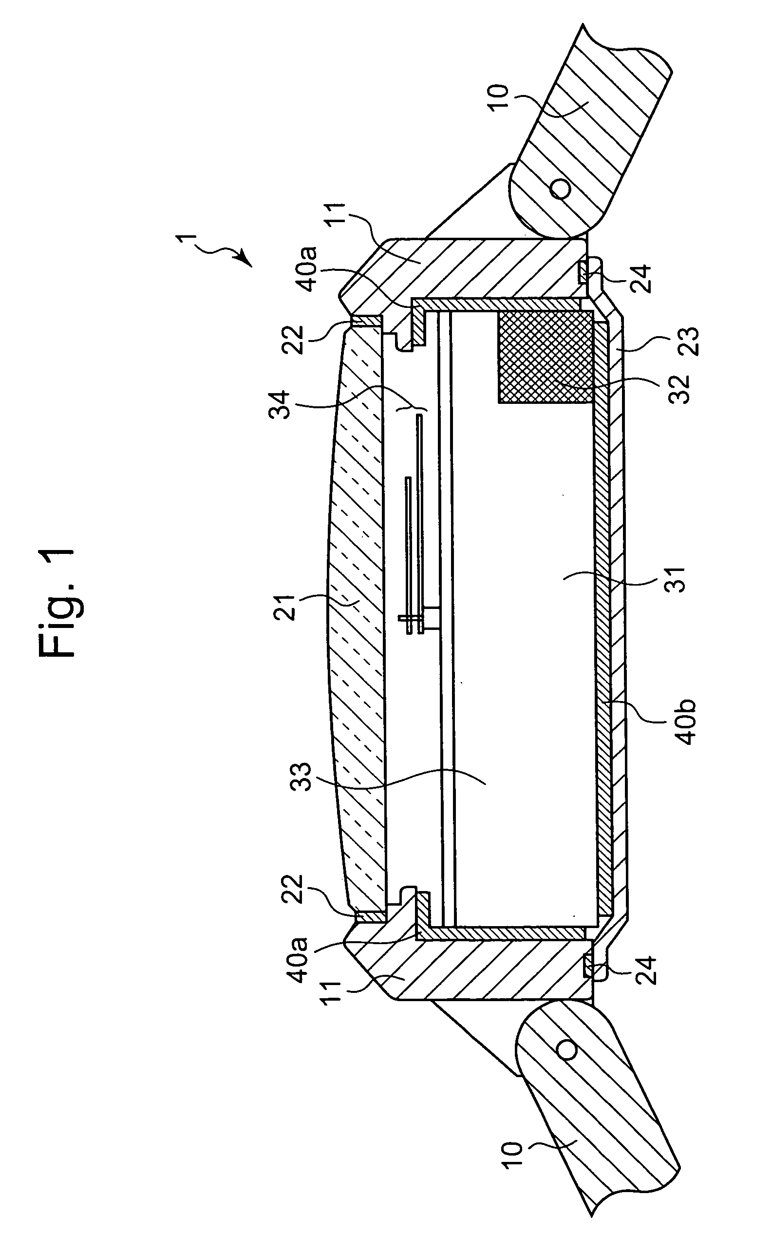
[0057]FIG. 2 is a schematic cross-sectional view of a wristwatch 2 according to the second embodiment. In the diagram, the right-hand side is the direction of 12 o'clock, and the left-hand side is the direction of 6 o'clock. Referring to FIG. 2, the wristwatch 2 has a watch case 12 and a back cover 23 which constitute a casing. The wristwatch 2 is a radio wave watch having an antenna 32 and a watch module 31.
[0058] The watch case 12 is formed of a synthetic resin, such as an ABS resin, and has an annular shape. A watch glass 21 is fitted in the watch case 12 via a packing 22 with a metal bezel 26 attached to the peripheral portion of the top surface of the watch case 12. The watch case 12 is provided with extending portions 13...
third embodiment
[0064] The third embodiment will be described below.
[0065] To avoid the redundant description, like or same reference numerals are given to those components of the third embodiment which are the same as the corresponding components of the first and second embodiments.
[0066]FIG. 3 is a schematic cross-sectional view of a wristwatch 3 according to the second embodiment. In the diagram, the wristwatch 3 has armoring components, such as a watch case 15, a back cover 23 and a bezel 27, which constitute a casing. The wristwatch 3 is a radio wave watch equipped with a watch module 31 having an antenna 32.
[0067] The watch case 15 is formed of a synthetic resin, and a bezel 26 of a metal is attached to the peripheral portion of the top surface of the watch case 15 to decorate the outer surface thereof. In the watch case 15, the antenna 32 is arranged above the back cover 23 and a face 33 is arranged further above.
[0068] Magnetic sheets 40b and 40e are respectively adhered to the inner su...
PUM
 Abstract
Description
Claims
Application Information