
Raman amplifier and raman pumping method

a wavelength division multiplexing and amplifier technology, applied in the field of raman amplifier of wavelength division multiplexing optical transmission system, can solve the problems of unstable output of pump laser, no pump laser whose output remains constant, transient phenomena, etc., and achieve the effect of wide signal bandwidth

Inactive Publication Date: 2005-06-09
INTELLECTUAL DISCOVERY CO LTD
View PDF9 Cites 8 Cited by
  • Summary
  • Abstract
  • Description
  • Claims
  • Application Information

AI Technical Summary

Benefits of technology

The present invention provides a way to get a flat amplification of signals in a wide range of frequencies. This means that the signal can be amplified equally across the entire range of frequencies. This is important for many applications where signals need to be transmitted over different networks or through different devices. The invention also provides a way to achieve this amplification using a special technique called Raman pumping. Overall, this invention allows for a more complete and accurate amplification of signals across a wide range of frequencies.

Problems solved by technology

However, in practice, there is no pump laser whose output remains constant when the wavelength of the pump laser changes.
Also, since a change in wavelength affects laser dynamics, outputs from pump lasers become unstable or transient phenomena occur when the wavelengths of the pump lasers change.

Method used


Image

  • Raman amplifier and raman pumping method
  • Raman amplifier and raman pumping method
  • Raman amplifier and raman pumping method

Examples


first embodiment

[0033]FIG. 4 illustrates the Raman pumping module according to the present invention.

[0034] Referring to FIG. 4, the Raman pumping module includes a light source unit 400, a light intensity control unit 410, and a control unit 420.

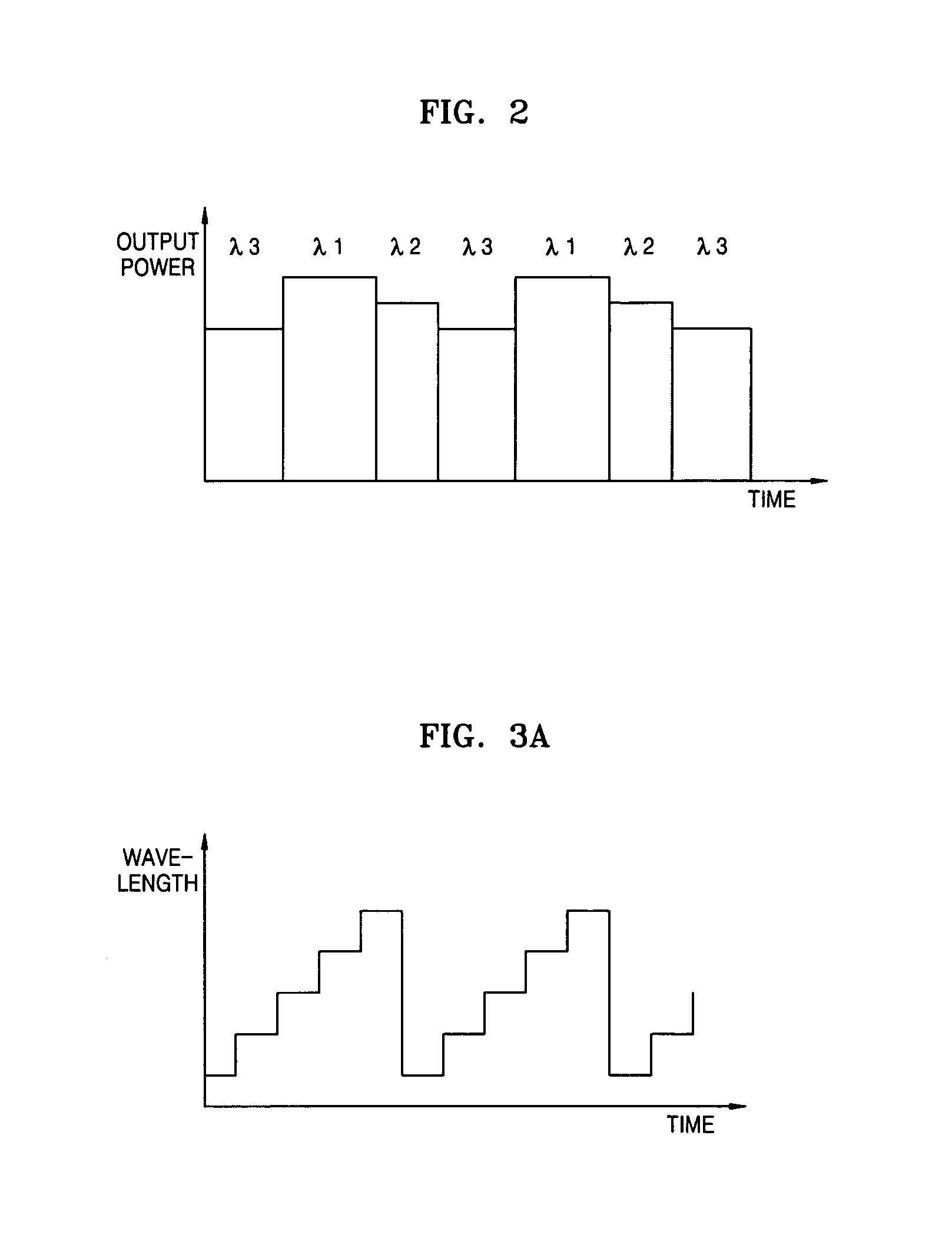
[0035] The light source unit 400 uses a pump laser of a wavelength that changes continuously or discretely over time within the predetermined range of wavelength. Exemplary outputs from a pump laser are shown in FIGS. 3A and 3B. In other words, the light source unit 400 outputs a pumping light with a wavelength that periodically changes.

[0036] The light source unit 400 may include a single pump laser with a wavelength that periodically changes or two pump lasers with wavelengths that periodically change. When the light source unit 400 includes two pump layers, the light source 400 includes a first light source 402, a second light source 404, and a polarized light beam coupler 406.

[0037] The first light source 402 outputs a first pumping light with a wav...

second embodiment

[0041]FIG. 5 illustrates the Raman pumping module according to the present invention.

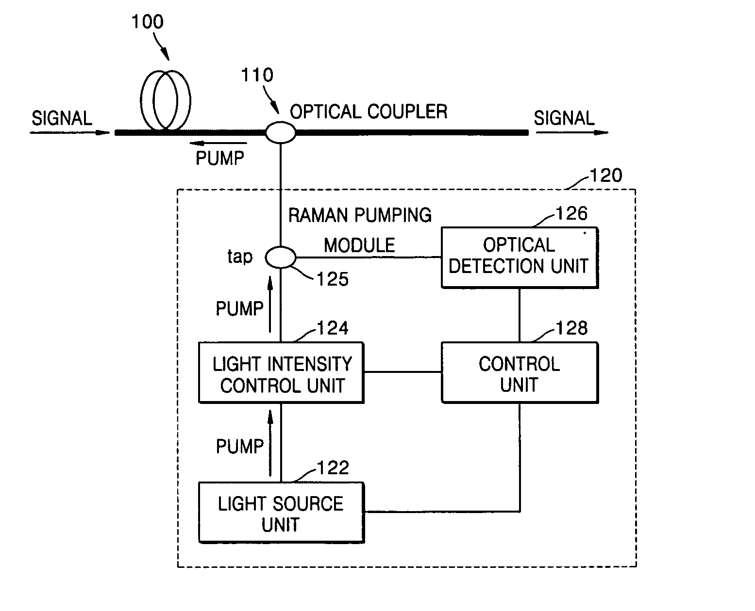
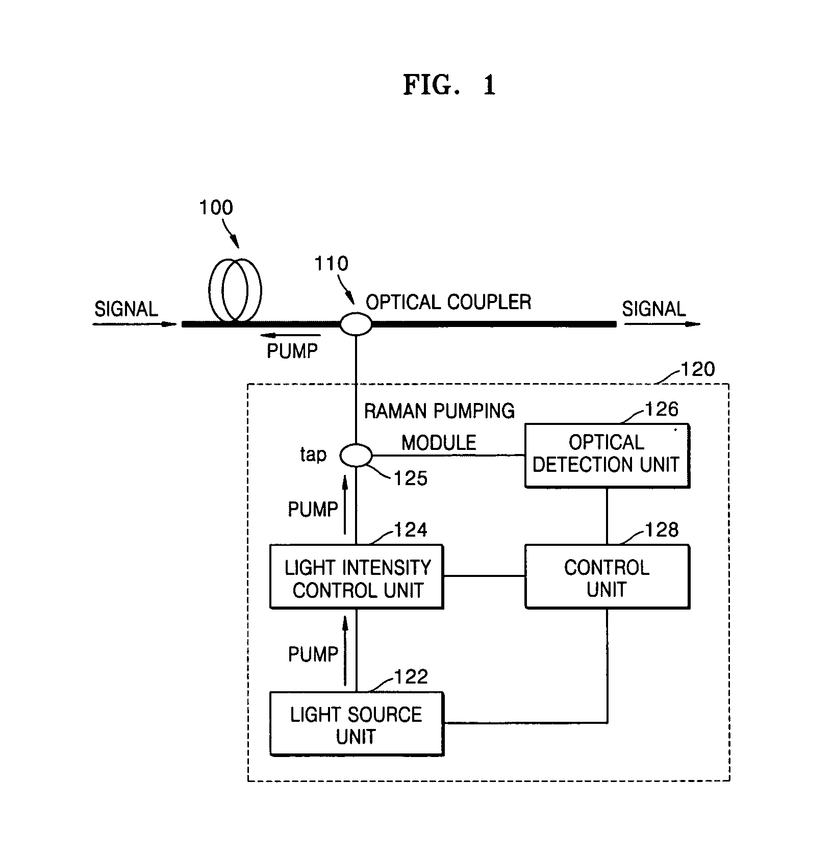
[0042] Referring to FIG. 5, the Raman pumping module includes a light source unit 500, a light intensity control unit 510, a control unit 520, a tap 530, and an optical detection unit 540. The configuration and operation of the light source unit 500 are the same as those of the light source 400 of FIG. 4 and will not be described here.

[0043] The tap 530 splits a portion of the pumping light output from the light intensity control unit 510. The split portion is output to the optical coupler 110 and the remaining portion is output to the optical detection unit 540.

[0044] The optical detection unit 540 detects the pumping light offer the portion of light has been split from it by the tap 530. More specifically, the light detection unit 540 outputs an electric signal (voltage or current) corresponding to the intensity of the input pumping light. The output electric signal is input to the control unit ...


PUM

PropertyMeasurementUnit
wavelengthaaaaaaaaaa
gain flatnessaaaaaaaaaa
light intensityaaaaaaaaaa

Abstract

Provided are a Raman amplifier and a Raman pumping method. A light source unit outputs a pumping light having a wavelength that periodically changes. A light intensity control unit varies a light intensity of the pumping light using the pumping light to improve the gain flatness of a Raman gain. A control unit directs the light intensity control unit to control the light intensity of the pumping light in synchronization with changes in the wavelength of the pumping light.

Description

CROSS REFERENCE TO RELATED APPLICATION [0001] This application claims the priority of Korean Patent Application No. 2003-70042, filed on Oct. 8, 2003, in the Korean Intellectual Property Office, the disclosure of which is hereby incorporated by reference in its entirety. BACKGROUND OF THE INVENTION [0002] 1. Field of the Invention [0003] The present invention relates to a Raman amplifier of a wavelength division multiplexing (WDM) optical transmission system. [0004] 2. Description of the Related Art [0005] In large-capacity WDM optical transmission systems, erbium-doped fiber amplifiers (EDFA) and Raman amplifiers are used to obtain a broad gain bandwidth and a small noise figure. [0006] The Raman amplifiers couple outputs from pump lasers of several different wavelengths using WDM optical couplers, send the coupled outputs from the pump lasers to optical fibers that is transmission paths, and amplify signal light. [0007] Raman amplifiers use a plurality of pump lasers of different ...

Claims


Application Information

Patent Timeline
Patent Type & Authority Applications(United States)
IPC IPC(8): H01S3/067G02F1/35H01S3/094H01S3/13H01S3/131H01S3/30
CPCH01S3/06754H01S3/094076H01S3/1301H01S3/1305H01S3/302H01S3/094096H01S3/13013H01S3/1001H04B10/291H04B10/2581
Inventor CHANG, SUN HYOKCHUNG, HEE SANGHAN, JIN SOOJUNG, JI SUNGPARK, HEUKLEE, WON KYOUNGLEE, HYUN JAE
Owner INTELLECTUAL DISCOVERY CO LTD
Learn More