
Optical network terminal and wavelength division multiplexing based optical network having the same

a wavelength division multiplexing and optical network technology, applied in the field of optical network terminals and wavelength division multiplexing based optical networks, can solve the problems of insufficient bandwidth and transmission quality of current digital subscriber lines (dsl) technologies using unshielded, utp) or cable modem termination systems (cmts) technologies using hybrid fiber coaxial (hfc) cables, and achieve the limitation of providing a broad bandwidth over 100 mbps, and high cost

Inactive Publication Date: 2005-06-09
ELECTRONICS & TELECOMM RES INST
View PDF6 Cites 30 Cited by
  • Summary
  • Abstract
  • Description
  • Claims
  • Application Information

AI Technical Summary

Benefits of technology

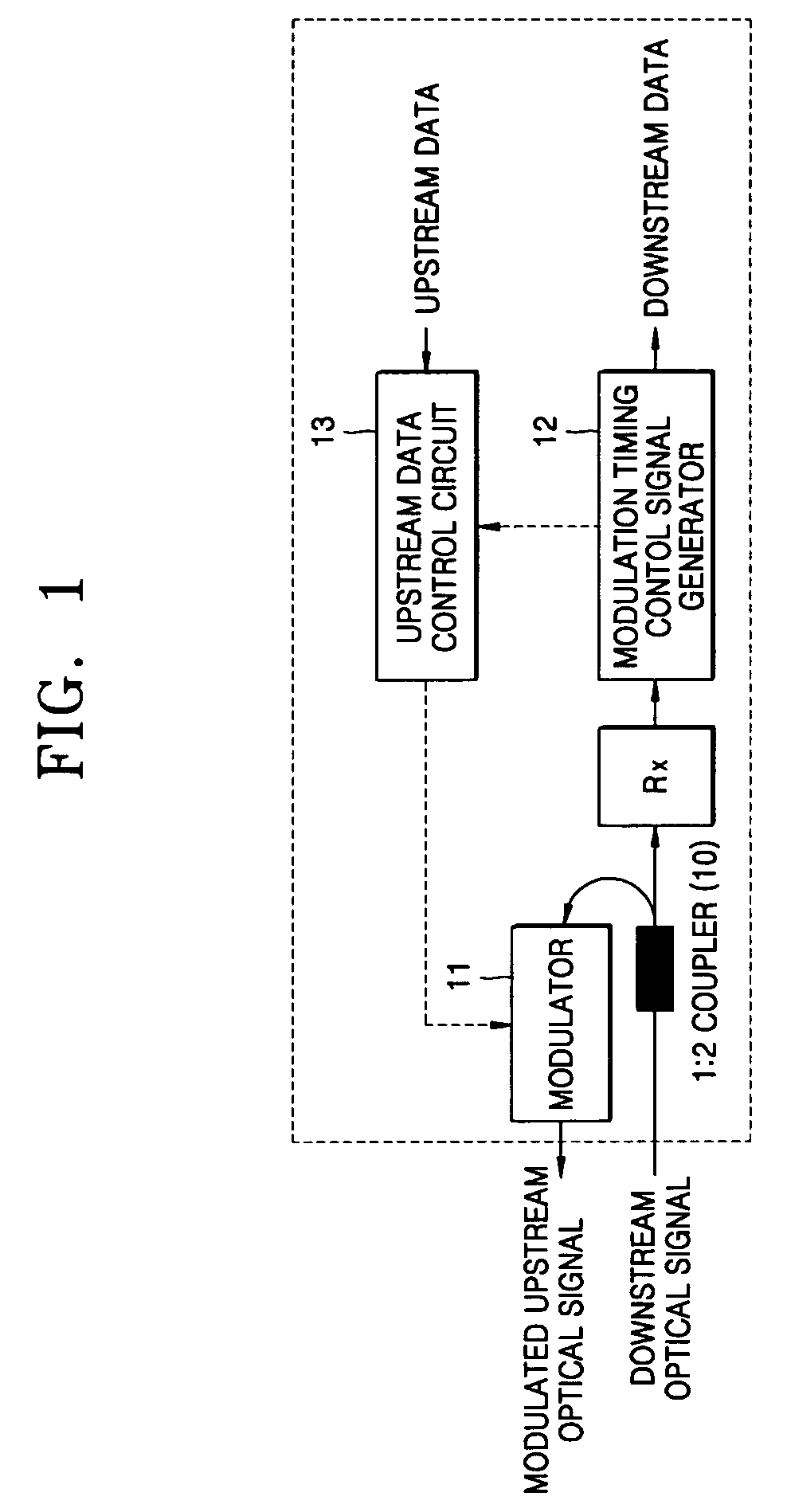
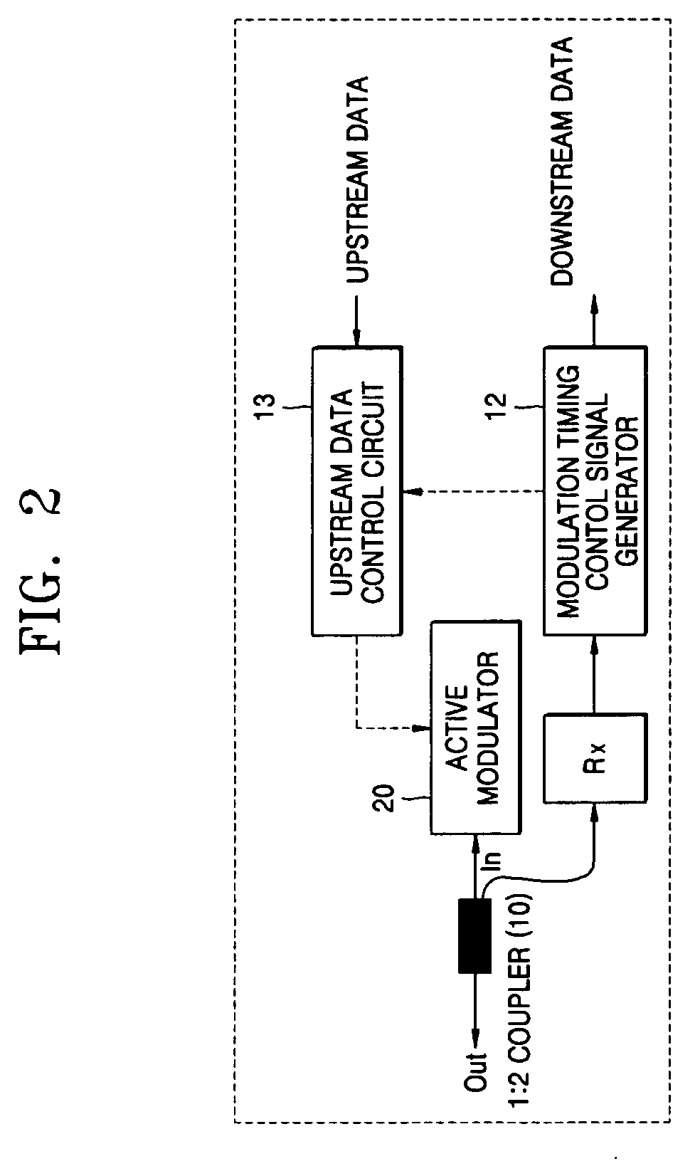
The present invention provides an optical network terminal that solves problems of high cost and large optical power loss in conventional loop-back ONT. It also provides a wavelength division multiplexing based optical network comprising this optical network terminal. The optical network terminal includes a modulation timing control signal generator, an upstream data control circuit, and a modulator. The modulation timing control signal generator receives a downstream optical signal and generates a timing control signal designating a start timing and an end timing for modulating an upstream optical signal to be transmitted from a user to the central office. The upstream data control circuit generates upstream data according to the timing control signal and controls modulation of the upstream optical signal according to the timing control signal in response to generation of the upstream data. The modulator receives the upstream data and directly modulates the upstream data using the downstream optical signal to produce the upstream optical signal and then output it to the central office. This optical network terminal solves problems of high cost and large optical power loss in conventional loop-back ONT.

Problems solved by technology

However, current digital subscriber line (DSL) technologies using a unshielded twisted pair (UTP) or cable modem termination system (CMTS) technologies using a hybrid fiber coaxial (HFC) cable would not guarantee sufficient bandwidths and transmission quality required to provide subscribers with such a high quality service.
Therefore, such a transmission method has limitation in providing a broad bandwidth over 100 Mbps required to guarantee transmission quality for future user's needs.
This causes additional workloads for producing, installing, and managing the N different ONTs, which will be a more serious problem when more and more ONTs are installed.
However, the EDFA is still very expensive so that it does not satisfy the cost-effectiveness as required for the subscriber access network.
Furthermore, this method has a limitation in a data modulation speed due to its innate optical characteristics, so that a high-speed modulation over 1 Gbps would be difficult to implement.
However, a conventional loop-back ONT has shortcomings that the Mach-Zehnder interferometer is expensive and has a large optical power losses (e.g., about 7˜10 dB, typically), and furthermore the downstream optical signal, which has experienced a lot of losses on the downstream path from the CO to the user, could not be reused to produce the upstream optical signal without amplification and then retransmit it to the CO.
In addition, it would be also expensive to employing a conventional loop-back ONT because an optical amplification still requires considerable expense.

Method used


Image

  • Optical network terminal and wavelength division multiplexing based optical network having the same
  • Optical network terminal and wavelength division multiplexing based optical network having the same
  • Optical network terminal and wavelength division multiplexing based optical network having the same

Examples


Embodiment Construction

[0033] For a convenient understanding of the present invention, first, we will discuss some operating conditions thereof in brief.

[0034] To achieve the above objects and solve the technical problems, the present invention proposes to use a Febry Perot laser diode (FP-LD) instead of a Mach-Zehnder modulator as an active modulator. Herein, the proposed modulator is referred to as “an active modulator” because input downstream optical signals are amplified and used for sending upstream data.

[0035] According to the present invention, a single mode light beam from a central office (i.e., a master light beam) is injected into the FP-LD, and among a plurality of wavelengths of the operation modes of the FP-LD, the closest mode to the wavelength of the injected master light beam becomes dominant over others. It is needed a procedure called “a wavelength tracking,” which uses a fact that the monitor photo diode (mPD) used to monitor the operating condition of the FP-LD produces a maximum o...


PUM


Abstract

Disclosed is a loop-back optical network terminal using a Febry-Perot laser diode as an active type optical modulator in a wavelength division multiplexing based optical network. In addition, a wavelength division multiplexing based optical network having the same is disclosed. The optical network terminal comprises a modulation timing control signal generator receiving a downstream optical signal transmitted from a central office and generating a timing control signal designating a start timing and an end timing for modulating an upstream optical signal to be transmitted from a user to the central office; an upstream data control circuit generating upstream data according to the timing control signal and controlling modulation of the upstream optical signal according to the timing control signal in response to generation of the upstream data; and a modulator receiving the upstream data and directly modulating the upstream data with loop-backing the downstream optical signal to produce the upstream optical signal and then output it to the central office.

Description

BACKGROUND OF THE INVENTION [0001] This application claims the priority of Korean Patent Application Nos. 2003-89070, filed on Dec. 9, 2003 and 2004-69556 filed on Sep. 1, 2004 in the Korean Intellectual Property Office, the disclosures of which are incorporated herein in their entirety by reference. [0002] 1. Field of the Invention [0003] The present invention relates to an optical network terminal (ONT) and a wavelength division multiplexing (WDM) based optical network having the same, and more particularly, to a loop-back ONT using a Febry Perot laser diode (FP-LD) as an active optical modulator, not as an optical source, in a WDM based optical network and a WDM based optical network having the same. [0004] 2. Description of the Related Art [0005] It is expected that the integrated triple play service of voice, data, and digital broadcasting service will be a major stream in communication services within several years. However, current digital subscriber line (DSL) technologies u...

Claims


Application Information

Patent Timeline
Patent Type & Authority Applications(United States)
IPC IPC(8): H04B10/26H04J14/00H04J14/02
CPCH04B10/2587H04J14/02H04J14/025H04J14/0282H04J14/0246H04J14/0226
Inventor KIM, BYOUNG WHIYANG, JAE WOOLEE, HYEONG HO
Owner ELECTRONICS & TELECOMM RES INST
Learn More