
Electrochemical cell having an improved safety

a technology of electrochemical cells and safety, applied in the direction of cell components, final product manufacturing, sustainable manufacturing/processing, etc., can solve the problems of hot box and nail penetration, cell safety associated with cell overcharge, and cell safety is urgently resolved, so as to improve the safety of the cell against the penetration of a needle-shaped conductor such as a nail

Active Publication Date: 2005-06-09
LG ENERGY SOLUTION LTD
View PDF6 Cites 11 Cited by
  • Summary
  • Abstract
  • Description
  • Claims
  • Application Information

AI Technical Summary

Benefits of technology

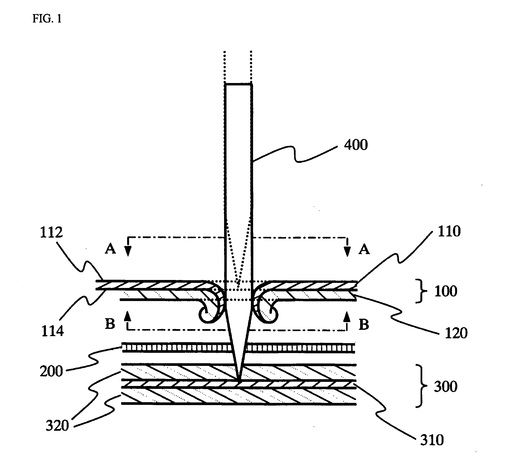
The present invention is about improving the safety of a cell against needle-shaped conductors such as nails. It does this by using a cathode with a thick cathode active material coated on one side and a cathode current collector coated on the other side. This arrangement covers both outer surfaces of the cell assembly, making it more resistant to needle puncture. The technical effect of this invention is to enhance the safety of cells in various applications where needle puncture is a potential risk.

Problems solved by technology

However, due to realization of high capacity of cells as described above, safety issues such as prevention of overcharge / over discharge and internal short-circuiting of cells have been increased.
In particular, cell safety associated with overcharge of cells, hot box and nail penetration is a urgently resolved problem.
However, use of the protective circuit is greatly limited to realization of small and inexpensive battery packs, while a heat blocking mechanism by separator does not work effectively in many cases, when heat generation occurs abruptly.
However, use of the organic electrolyte additive may give rise to deterioration of cell performance.
However, the above-mentioned methods have failed to elevate an initial temperature at which the surface of the electrode active material reacts with the electrolyte, i.e., a temperature (a heat generation temperature) at which oxygen molecules combined with metals of the cathode active material are liberated, on overcharging the cell, and also have failed to decrease a heat value.
In addition, U.S. Pat. No. 5,705,291 discloses a method for increasing structural stability of a cathode active material, by coating the surface of the cathode active material with a composition containing borate, aluminate, silicate, or mixtures thereof, but this method still exhibits poor structural stability.

Method used


Image

  • Electrochemical cell having an improved safety
  • Electrochemical cell having an improved safety
  • Electrochemical cell having an improved safety

Examples


example 1

Preparation of a stacked cell having a single-side coated cathode as the outermost electrode

1.1. Preparation of Cathode

[0030] LiCoO2, carbon black and PVDF, in a weight ratio of 95:2.5:2.5, were dispersed in NMP to prepare a slurry. The slurry thus obtained was coated on a sheet of aluminum foil, sufficiently dried at a temperature of 130° C. and then roll-pressed to prepare a cathode.

[0031] In this connection, the cathode, which is to be positioned on the outermost side of the outermost bicell, was coated with the slurry on one side of the aluminum foil only (“single side coating”), while the cathode of the bicell, which is to be positioned inside thereof, was coated with the slurry on both sides of the aluminum foil.

[0032] The aluminum foil, which is a cathode current collector in the single-side coated cathode, was made to have a thickness corresponding to 50%, 60%, 70%, 80%, 90% and 100% of that of the cathode active material coated layer, respectively. The thickness of the...


PUM

PropertyMeasurementUnit
temperatureaaaaaaaaaa
thicknessaaaaaaaaaa
thicknessaaaaaaaaaa

Abstract

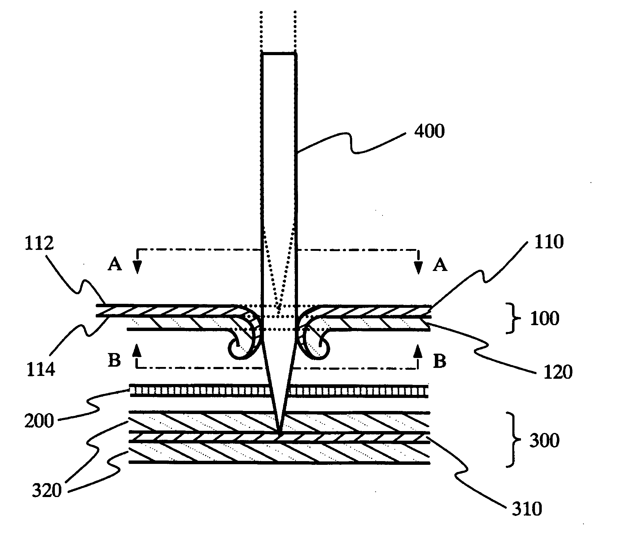
Provided is a cell wherein out of electrodes constituting the cell, the outermost two electrodes are both cathodes, cathode current collectors of the cathodes are single-side coated with cathode active materials on the first surfaces thereof, other sides of cathode current collectors non-coated with cathode active materials are disposed toward the outside of a cell assembly and the thickness of cathode current collectors is 70 to 150% of that of the cathode active material coated layer. The cell in accordance with the present invention exhibits excellent safety in a nail penetration test.

Description

FIELD OF THE INVENTION [0001] The present invention relates to an electrochemical cell having improved safety. BACKGROUND OF THE INVENTION [0002] An interest in energy storage technology has been increased. In particular, applications of electrochemical devices have been extended to portable telecommunication instruments such as compact mobile phones, camcorders and notebook computers, and further a power source for electric vehicles, and thereby efforts and attempts to research and develop such electrochemical devices are increasingly actualized. In this respect, the field of electrochemical energy storage devices has occupied a great deal of attention, and in particular, a lot of interest has been focused on the development of rechargeable secondary batteries. [0003] Further, as a result of miniaturization and weight reduction of electric instruments, miniaturization and weight reduction of batteries used as a power source of the electronic instruments are also demanded. Therefore...

Claims


Application Information

Patent Timeline
Patent Type & Authority Applications(United States)
IPC IPC(8): H01M4/13H01M10/04H01M10/05H01M10/0525H01M10/0585
CPCH01M4/04H01M4/0404H01M4/70H01M10/04Y02T10/7011H01M10/0525H01M10/0585H01M10/38H01M10/4235H01M10/0413H01M10/058Y02E60/10Y02P70/50H01M10/0583
Inventor KANG, HEE GYOUNGHYUN, OH YOUNGAHN, CHANG BUMLEE, HYANG MOK
Owner LG ENERGY SOLUTION LTD
Learn More