Post patch for mounting devices inside tires

a technology for mounting devices and tires, applied in the field of system, method and apparatus for mounting electrical and electronic components and assemblies in tires, can solve the problems of not being able to generally address all the above-referenced concerns, and achieve the effect of facilitating the electronic system bonding and simplifying the electronics portion

Inactive Publication Date: 2005-06-16
MICHELIN RECH & TECH SA
View PDF17 Cites 43 Cited by
  • Summary
  • Abstract
  • Description
  • Claims
  • Application Information

AI Technical Summary

Benefits of technology

[0021] Another advantage in accordance with certain embodiments of the present technology lies in providing improved technology for mounting an electronic device on the inside of a tire while decoupling the electronic device from the mechanical stress, vibration, and heat generation associated with the rotation of the tire.
[0022] Yet another advantage in accordance with certain embodiments of the presently disclosed technology is that techniques are provided for simplifying the attachment of the electronics portion of the electronics device to the mounting patch. This corresponds in one exemplary embodiment to gluing an encapsulated “tag” assembly directly to a portion of the mounting post followed by encapsulation of the glued, encapsulated tag assembly and a portion of the mounting post. In another exemplary embodiment, an electronic device is potted into a rigid housing that is then directly glued to a portion of the mounting post.
[0023] A still further advantage of certain embodiments of the present subject matter is that improved bonding of the tire electronics system is facilitated by providing contoured platforms to fit within the contour of the tag assembly. This corresponds in one exemplary embodiment to the provision of a post platform having an outer contour shaped like the footprint of the tag assembly.
[0024] Yet a further advantage of certain embodiments of the present subject matter is that certain vibration transmission modes are suppressed. In one exemplary embodiment of the presently disclosed technology this corresponds to the provision of specifically shaped posts connecting the electronic device supporting platform to the tire inner liner attachment portion of the mounting patch.

Problems solved by technology

While various tire monitoring patch and electronics systems have been developed, no one design has emerged that generally addresses all of the above-referenced concerns and that encompasses all of the desired characteristics as hereafter presented in accordance with the subject technology.

Method used


Image

  • Post patch for mounting devices inside tires
  • Post patch for mounting devices inside tires
  • Post patch for mounting devices inside tires

Examples


first embodiment

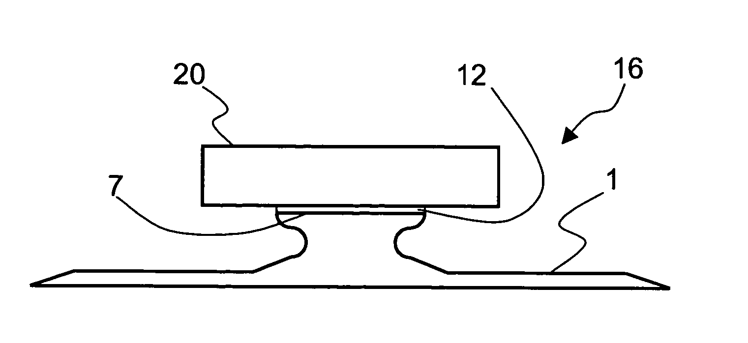
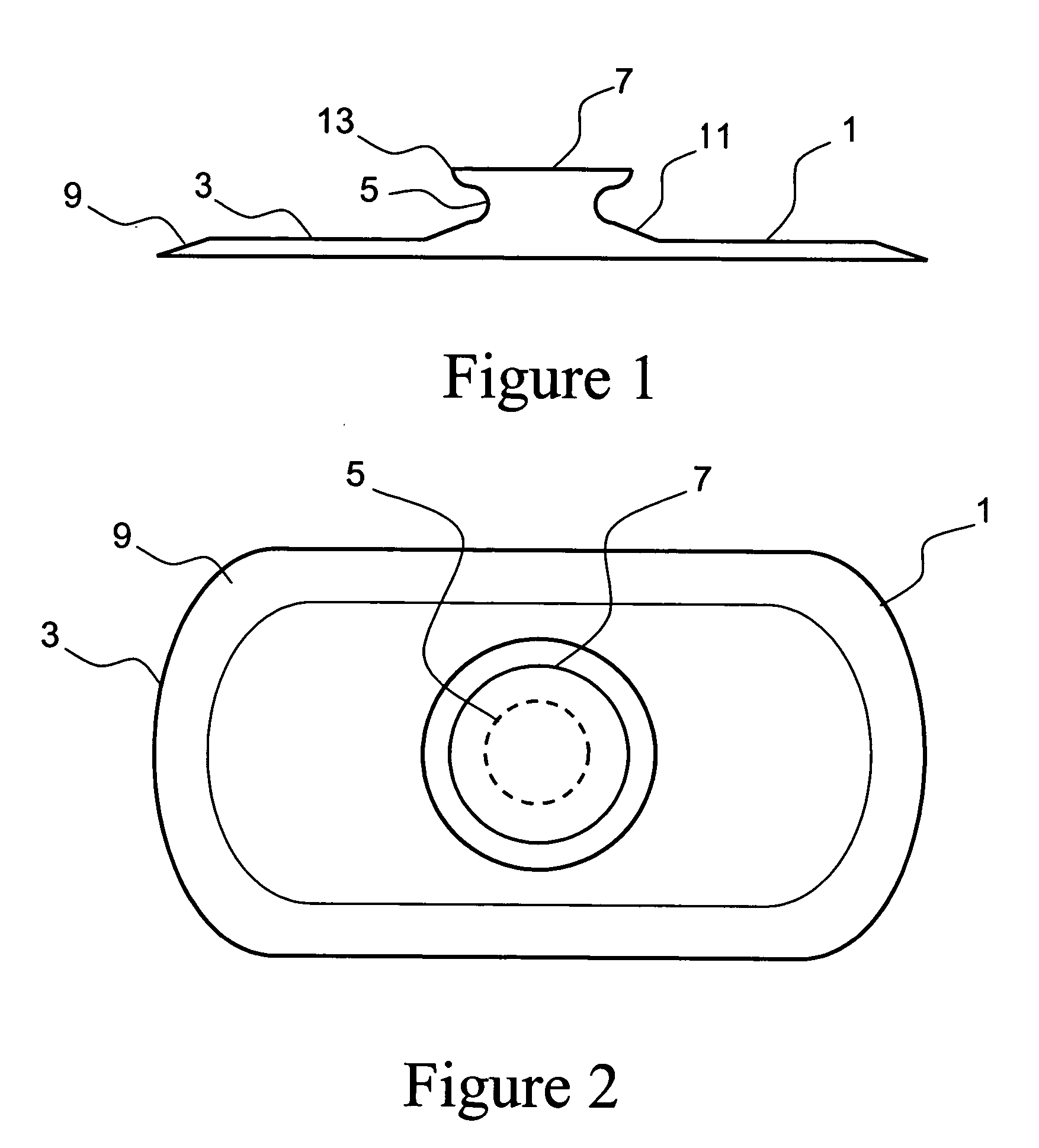
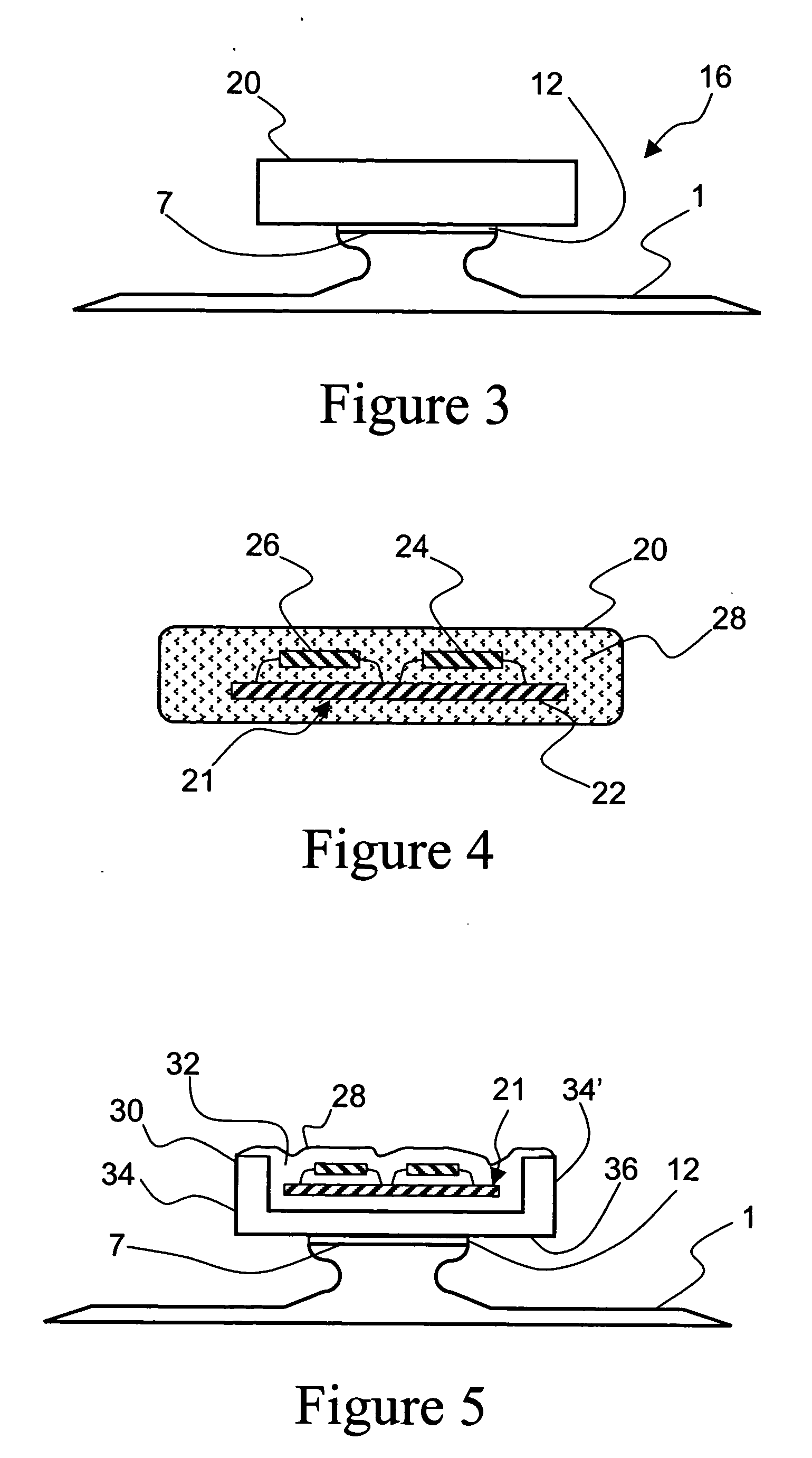
[0044] With particular reference to FIGS. 1 and 2, there are illustrated, respectively, side and top views of a tire patch 1 in accordance with the presently disclosed subject matter. The tire patch 1 is composed of a vulcanized rubber compound and comprises three major components: a base 3 for attachment to the inner liner of a tire, a platform 7 for supporting variously selected electronic components, and a pillar 5 for coupling the base 3 to the platform 7 and providing at least partial isolation or decoupling of any electronic devices which may be mounted on the platform 7 from road and tire induced conditions that may adversely effect electronic devices supported by tire patch 1. In addition to these three major components, several other features of tire patch 1 are significant. Edges 9 of the base 3 may be feathered to avoid stress concentration around the perimeter of the base. The generally oval shape of the base 3, as best seen in FIG. 2, also assists in avoiding stress con...

embodiment 19

[0051] A fourth patch assembly embodiment 19 of the present subject matter is illustrated in FIGS. 11 and 12. As in the previous two embodiments, the tire patch 1 illustrated in FIGS. 11 and 12 retains all of the features previously illustrated except for the pillar. In this embodiment, the pillar 5″ has an outer contour shaped like a cross. It has been found that this cross-shaped contour provides a higher level of rejection of some frequency modes, thus providing improved decoupling of any electronic device 20 which may be affixed to the platform 7 from stress and vibration transmitted to the electronic device 20 from the tire as it comes into contact with a traveled surface.

[0052] Now with reference to FIG. 13, an exemplary tire assembly embodiment 28 of the present invention is illustrated wherein a patch assembly 16 is mounted within a pneumatic tire 30. Although reference numeral 16 is used here to represent the exemplary patch assembly integrated with pneumatic tire 30, it sh...


PUM

PropertyMeasurementUnit
stress concentrationaaaaaaaaaa

Abstract

A system, method and apparatus for mounting electrical and electronic components and devices for integration with a pneumatic tire includes a specially configured mounting patch for mounting at least one electronic device supported by a substrate. The mounting patch is preferably adapted for positioning on the inner liner of a pneumatic tire and is configured to decouple any mounted electronic device from tire related phenomena including mechanical stress, vibration, heat, and other adverse effects generated from rotational operation of the tire. Exemplary mounting patches include circular or rectangular platforms for supporting various electronic components and circular, rectangular or cross-shaped pillars coupling the base of the mounting patch to electronic device supporting platform. Selected of the electronic devices may be encapsulated by a potting material to facilitate effective attachment of the electronic devices to the tire patch.

Description

FIELD OF THE INVENTION [0001] The present invention generally concerns a system, method and apparatus for mounting electrical and electronic components and assemblies in a tire. The subject matter disclosed relates to mounting patches and techniques for mounting power source(s), circuit boards, and other electronic devices on so called “patch” elements within a tire. BACKGROUND OF THE INVENTION [0002] The incorporation of electronic devices with and within pneumatic tire structures yields many practical advantages. Tire electronics may include sensors and other components for obtaining information regarding various physical parameters of a tire, such as temperature, pressure, number of tire revolutions, vehicle speed, revolutions at speed, revolutions at temperature, etc. Such performance information may become useful in tire monitoring and warning systems, and may even potentially be employed with feedback systems to regulate proper tire pressure levels. [0003] One of many potentia...

Claims


Application Information

Patent Timeline
Patent Type & Authority Applications(United States)
IPC IPC(8): B60C19/00G08C19/00B60C23/04B60C23/20G08C17/02
CPCY10T152/10882B60C23/0493
Inventor FORNEROD, PIERREMETCALF, ARTHUR RICHARDSINNETT, JAY CLIFFORD
Owner MICHELIN RECH & TECH SA
Why Eureka
Try Eureka