Tire manufacturing module and method of manufacturing tires

a tire manufacturing module and tire technology, applied in the direction of belts, transportation and packaging, other domestic articles, etc., can solve the problems of aging, components are often stored, and require a large work area for two separate positions,

Inactive Publication Date: 2005-06-16
THE GOODYEAR TIRE & RUBBER CO
View PDF12 Cites 26 Cited by
  • Summary
  • Abstract
  • Description
  • Claims
  • Application Information

AI Technical Summary

Benefits of technology

[0035] It is preferable that the step of applying the tire components includes the step of forming one or more of the tire components at the locations where the component is applied. It is further contemplated that the step of forming includes the step of extruding strips of elastomeric rubber. The above method permits the tire to be formed, applied, and cured in a small module. This module permits the manufacture of tires in very small lot sizes.
[0036] In order to change tire sizes or to build another tire construction the module has software pre-programmed to the specific tire construction. A simple changing of the mold permits the manufacture of different tires of different sizes and styles. Additionally, different tire building drums are applied to the trolley to permit the manufacture of different sizes of tires. The above-manufacturing module permits small production lots to be produced in a very efficient manner. Definitions
[0045]“Chafer” refers to reinforcing material (rubber alone, or fabric and rubber) around the bead in the rim flange area to prevent chafing of the tire by the rim parts.

Problems solved by technology

While the two-stage building process in its separate stages accommodated servers for the various components, it presented the problems of requiring a large work area for the two separate positions and the need to coordinate the separate functions as well as bringing all of the components together at the proper stations.
As a result, the components were often stored and became subject to aging, sometimes losing their tack, for example, during the handling of the individually applied components.
Moving the tire subassemblies from one stage to another has been a highly labor intensive operation even with the use of mechanical servers to assist operators in placing the components on the tire on the first and second stage drums.
As a result, the operation was costly.
While this system, has overcome some floor space problems, its output is still limited.
Also, as disclosed in U.S. Pat. No. 1,818,955, tires can be manufactured on a line with a plurality of building drums “arranged in a train or series and a connecting means is provided for translating the cores from one device to the next.” The connectivity between the tire cores (building drums) leads to the inability to change the machine to accommodate various sized tire constructions.
Further, as disclosed in U.S. Pat. No. 5,354,404, there is illustrated another system for manufacturing tires on a line with a plurality of building drums “arranged in a train or series and a connecting means is provided for translating the cores from one device to the next.” The connectivity between the tire building cores leads to the inability to change the machine to accommodate various sized tire constructions.
The problem with these prior art manufacturing systems is that the location and position of the building drums was not precise enough to ensure that the tires being constructed were of adequate uniformity for the requirements of present day high performance tires.
That is, while the tire building drums moving along the assembly path were stopped at a stop position at each work position, there is no teaching or suggestion of how the position of the tire building drum was positioned at a precise position.
This would suggest that each drum is more complicated and expensive to produce.
For example, a tread which “snakes” as it goes around the tire circumference will cause wobbling as the tire is operated.
For example, a carcass ply which is lopsided (longer cords on one side of the tire than the other side) can cause a variety of tire non-uniformity problems including static imbalance and radial force variations.
For example, a tire which is not meridionally symmetric (e.g., tread not centered between beads) can cause a variety of tire non-uniformity problems including couple imbalance, lateral force variations, and conicity.
The prior art, as discussed herein still has problems of enabling the building of tires with complicated construction, such as runflat tires, to be built on a single manufacturing line that is capable of being easily changed to accommodate different constructions sizes.
A primary limitation of the above-described prior art method of automated tire assembly is believed to be the applying of the components for the carcass assembly on a flat building drum and then inflating said drum to a toroidal shape prior to applying the belt tread assembly.
Another primary limitation is the application of the tread belt assembly to the toroidially shaped carcass means.

Method used


Image

  • Tire manufacturing module and method of manufacturing tires
  • Tire manufacturing module and method of manufacturing tires
  • Tire manufacturing module and method of manufacturing tires

Examples


Embodiment Construction

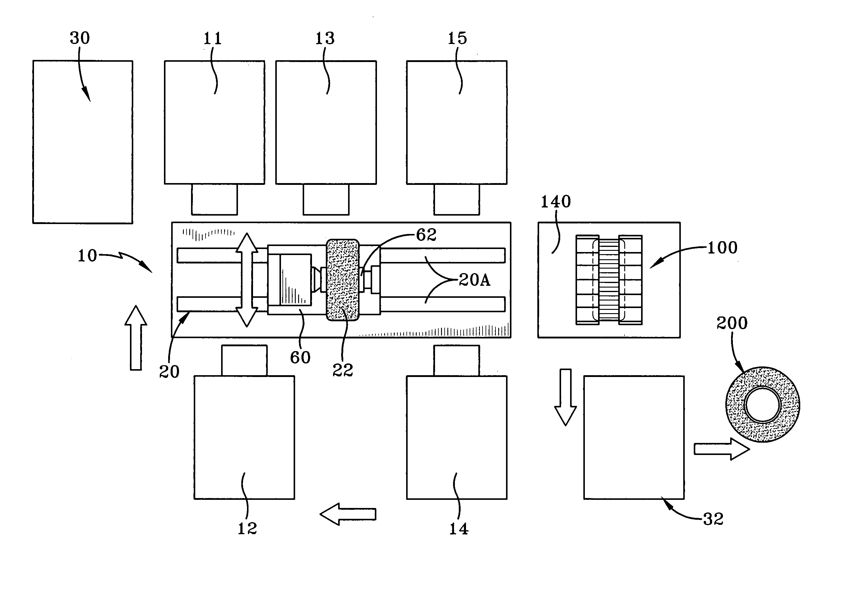
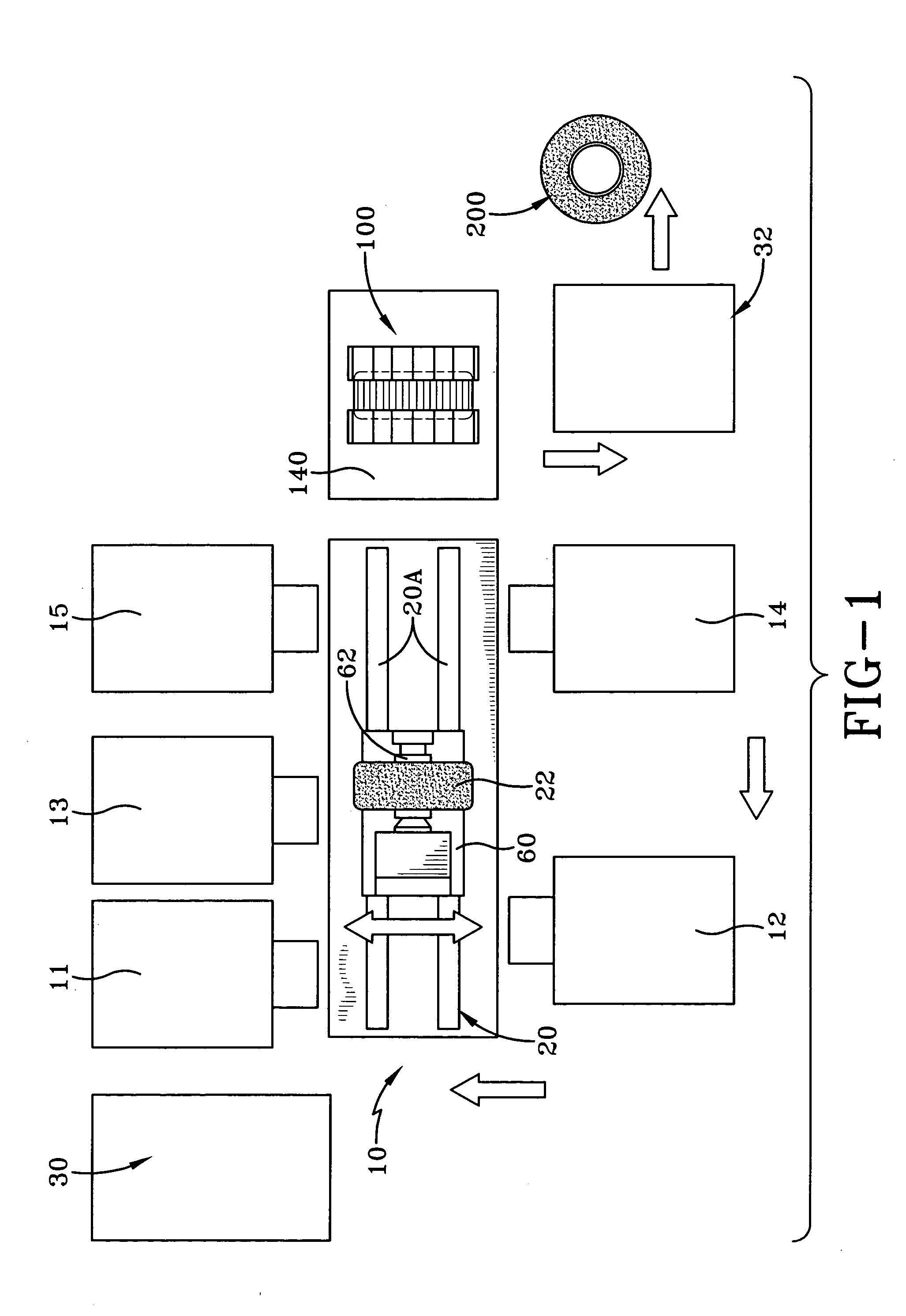
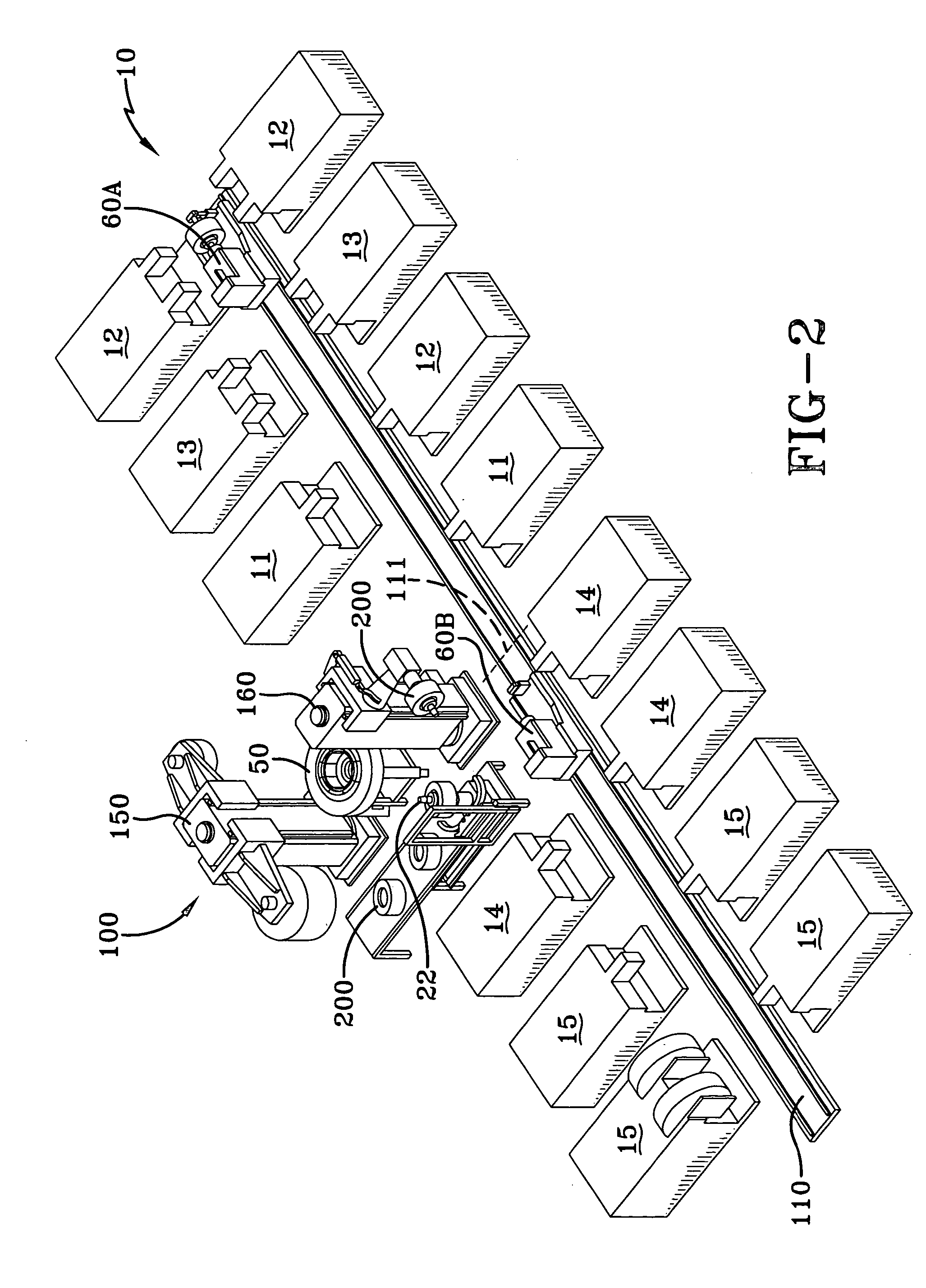
[0074] With reference to FIGS. 1 and 2 schematic views of an automated tire manufacturing module 10 according to the present invention are illustrated. This system or module 10 provides for the complete manufacture of pneumatic tires and provides up to two simultaneously operating tire building stations and one tire curing station in one module. This module 10 forms the tire carcass subassembly 4 and the tire belt tread subassembly 3. As shown in FIG. 7, these two subassemblies 3, 4 after being assembled on a detachable building drum 22 and inserted while on the building drum into a tire curing mold 50 after their assembly is completed. When at the tire curing mold, the mold 50 will then be closed and heated at a mold curing station 100 which permits the tires 200 to be cured or otherwise vulcanized and removed from the mold 50 and the building drum 22.

[0075] As shown the FIGS. 1 and 2 at the initial building of a tire there is a mobile tire building trolleys 60, 60A with a specifi...


PUM

PropertyMeasurementUnit
cord anglesaaaaaaaaaa
anglesaaaaaaaaaa
of rotationaaaaaaaaaa

Abstract

A module for manufacturing a cured tire from a plurality of tire components is disclosed. The module has a plurality of component appliers located at spaced locations along a predetermined path, and a mobile tire building trolley for movement along the predetermined path and two detachable tire building drums for mounting on the movable trolley. A tire curing station has one tire mold for curing the assembled tire components while mounted on one of the detachable tire building drums. The tire is cured as the other detachable tire building drum on the mobile tire building trolley is having tire components applied. One or more of the plurality of component appliers includes a means for forming the tire component at the location of the applier. The applied components include a liner, a pair of bead cores, a ply, a pair of sidewalls, a pair of chafers, and one or more belt layers and a tread. Optionally the applied components may also include an apex, wedges, overlays, underlays, gum strips, and elastomeric inserts. The module has a means for transferring the detachable tire building drums to the tire mold and further has a means for extracting the cured tire while mounted on a tire building drum from the mold. The tire curing station includes an induction curing means.

Description

CROSS-REFERENCE TO RELATED APPLICATIONS [0001] This application relates to the following U.S. patent applications entitled: “A Method and Apparatus for forming an Annular Elastomeric Tire Component”, U.S. Ser. No. 10 / 291,279, filed on Nov. 8, 2002; “An Improved Method and Apparatus for Manufacturing Carcass Plies For a Tire”, U.S. Ser. No. 10 / 365,374, filed on Feb. 11, 2003; “Radially Expansible Tire Assembly Drum and Method For Forming Tires”, Ser. No. 10 / 388,773, filed Mar. 14, 2003; “Method and Apparatus For Tread Belt Assemblies”, Docket No. DN2003-078, filed on May 20, 2003; and “A Method For Curing Tires and a Self-Locking Tire Mold”, U.S. Ser. No. 10 / 417,849, filed Apr. 17, 2003; “Method for Manufacturing Tires on a Flexible Manufacturing System, U.S. Ser. No. 10 / 449,468, filed May 30, 2003.FIELD OF THE INVENTION [0002] The present invention relates to automated tire manufacturing machines and more particular to methods and apparatus for simultaneously assembling a purality o...

Claims


Application Information

Patent Timeline
Patent Type & Authority Applications(United States)
IPC IPC(8): B29D30/00B29C35/08B29D30/06B29D30/10B29D30/16
CPCB29C2035/0811B29D30/0601B29D30/0661B29D2030/105B29D30/1635B29D2030/0682B29D30/10B29D30/16
Inventor SIEVERDING, MARK ANTHONYGIRARD, JEAN-CLAUDECURRIE, WILLIAM DUDLEYHENTHORNE, DAVID ALANLUNDELL, DENNIS ALAN
Owner THE GOODYEAR TIRE & RUBBER CO
Why Eureka
Try Eureka