Wear indicator for seal strip in a suction box of a paper machine

a technology of suction box and seal strip, which is applied in the field of paper machines, can solve the problems of reduced life expectancy of seal strips, affecting the quality of sealing, and affecting the appearance of sealing strips, etc., and achieves the effect of accurate indication of the wear state of seal strips and simplified construction

Inactive Publication Date: 2005-06-16
VOITH PATENT GMBH
View PDF13 Cites 23 Cited by
  • Summary
  • Abstract
  • Description
  • Claims
  • Application Information

AI Technical Summary

Benefits of technology

[0010] An advantage of the present invention is that the sensor is coupled with a fixed surface, thereby simplifying construction and providing a more accurate indication of the wear state of the seal strip.
[0011] Another advantage is that the target sensed by the sensor may be of multiple differ...

Problems solved by technology

Due to frictional contact between the seal strips and the suction roll, wear occurs on the seal strips and the inside diameter of the suction roll, resulting in a reduced life expectancy for the seal strips.
This type of sensor arrangement is bulky and therefore requires large seal strips to accommodate the sensor.
Moreover, modifying the seal strip affects the structur...

Method used


Image

  • Wear indicator for seal strip in a suction box of a paper machine
  • Wear indicator for seal strip in a suction box of a paper machine

Examples


Embodiment Construction

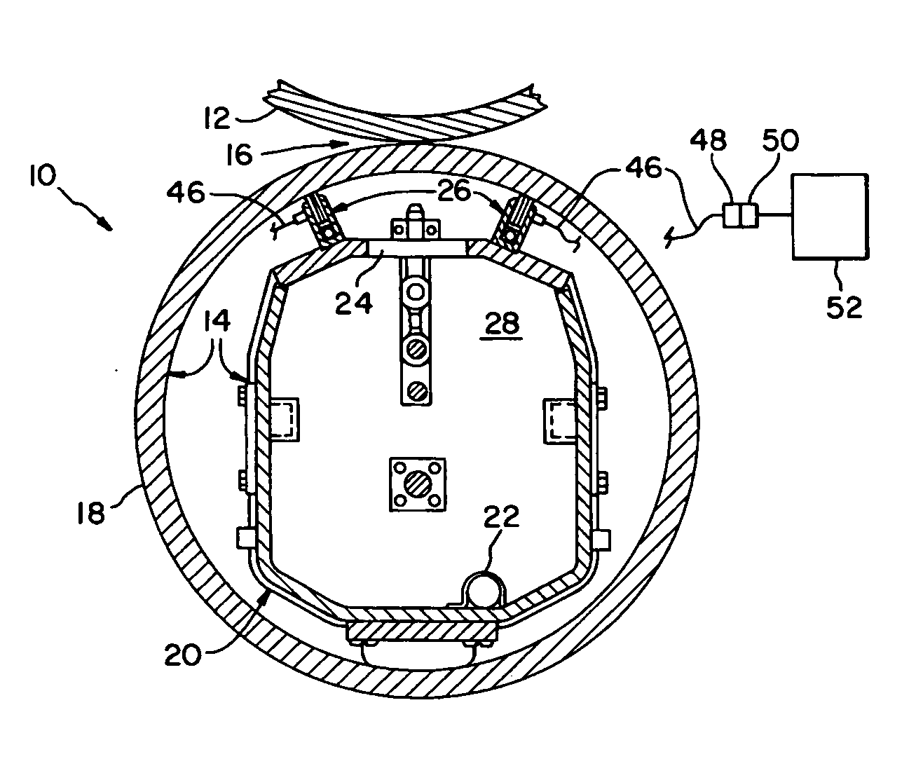
[0018] Referring now to the drawings, there is shown an embodiment of a paper machine 10 of the present invention, including press roll 12 and suction roll assembly 14 at the wet end of the paper machine. Paper machine 10 typically includes other components (not shown), such as a head box, wire section, forming section, drying section, etc. Press roll 12 and suction roll assembly 14 define a nip 16 therebetween, through which a fiber web (not shown) may pass. Press roll 12 and / or suction roll assembly 14 may also carry a belt, felt and / or wire (not shown) for transporting the fiber web through nip 16.

[0019] Suction roll assembly 14 generally includes a suction roll 18 and a suction box 20. Suction roll 18 has a foraminous (i.e., perforated) shell through which liquid may pass. The types and sizes of perforations may vary from one application to another, and therefore are not shown as a conventional feature in FIG. 1 for simplicity sake.

[0020] Suction box 20 is stationarily positio...


PUM


Abstract

A suction roll assembly includes a suction roll having a perforated shell, and a suction box positioned within the suction roll. The suction box includes a holder, a seal strip adjacent the shell and carried by the holder, at least one target carried by the seal strip, and at least one sensor positioned in association with at least one target. Each sensor provides an output signal indicative of a position of at least one corresponding target.

Description

BACKGROUND OF THE INVENTION [0001] 1. Field of the Invention [0002] The present invention relates to paper machines, and, more particularly, to wear indicators for seal strips used in a suction box. [0003] 2. Description of the Related Art [0004] Paper machines generally include a wet end and dry end of the machine. The wet end of the machine generally can be broken down into further components, such as the head box, forming section, press section, etc. Likewise, the dry end of the machine can be broken down into further components including a dryer section, winder, etc. The wet end of the machine typically includes a number of suction roll assemblies. A suction roll assembly typically includes a suction roll and suction box placed within the suction roll. The suction roll includes a perforated cylindrical shell that is rotatably supported together with the stationary suction box disposed internally thereof and connected with a source of vacuum. The suction box includes a slot like ...

Claims


Application Information

Patent Timeline
IPC IPC(8): D21F3/10
CPCD21F3/10
Inventor GLEASON, JAMES JR.
Owner VOITH PATENT GMBH
Why Eureka
Try Eureka