Membrane separation device and membrane separation method

a membrane separation and membrane technology, applied in the direction of membranes, filtration separation, separation processes, etc., can solve the problem of inferior membrane packing efficiency

Inactive Publication Date: 2005-06-16
KOBELCO ECO-SOLUTIONS CO LTD
View PDF3 Cites 27 Cited by
  • Summary
  • Abstract
  • Description
  • Claims
  • Application Information

AI Technical Summary

Benefits of technology

[0020] With the above preferable arrangement in which the adjacent membrane separation element groups are disposed at a certain angle (e.g., orthogonal) relative to each other, it is easy to cause turbulent flow of water to be treated. As a result, deposition of suspended solid on memb

Problems solved by technology

This is advantageous in that plugging is unlikely to occur in flow passages of the tubes, but has a shortcoming in that the va

Method used


Image

  • Membrane separation device and membrane separation method
  • Membrane separation device and membrane separation method
  • Membrane separation device and membrane separation method

Examples


examples

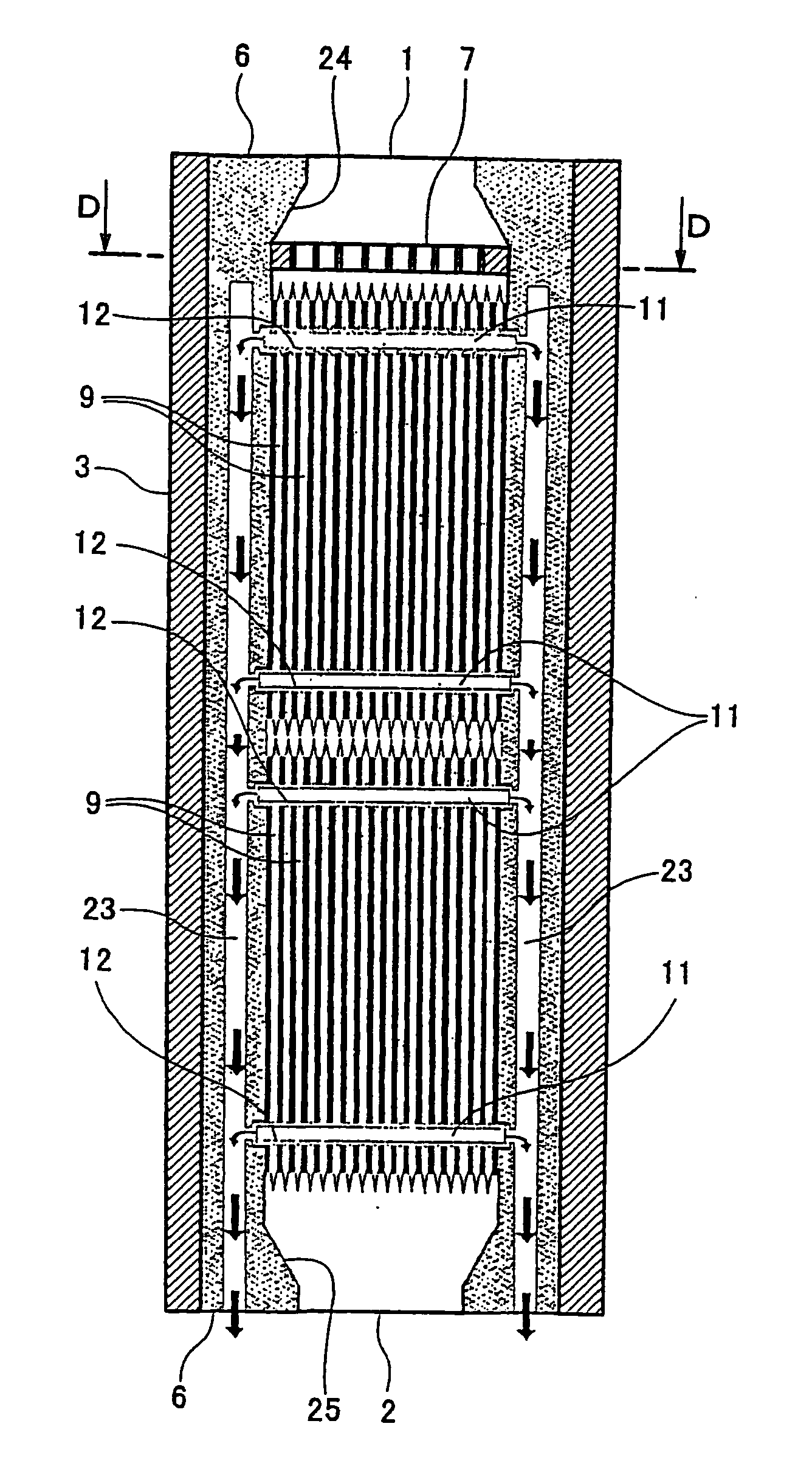
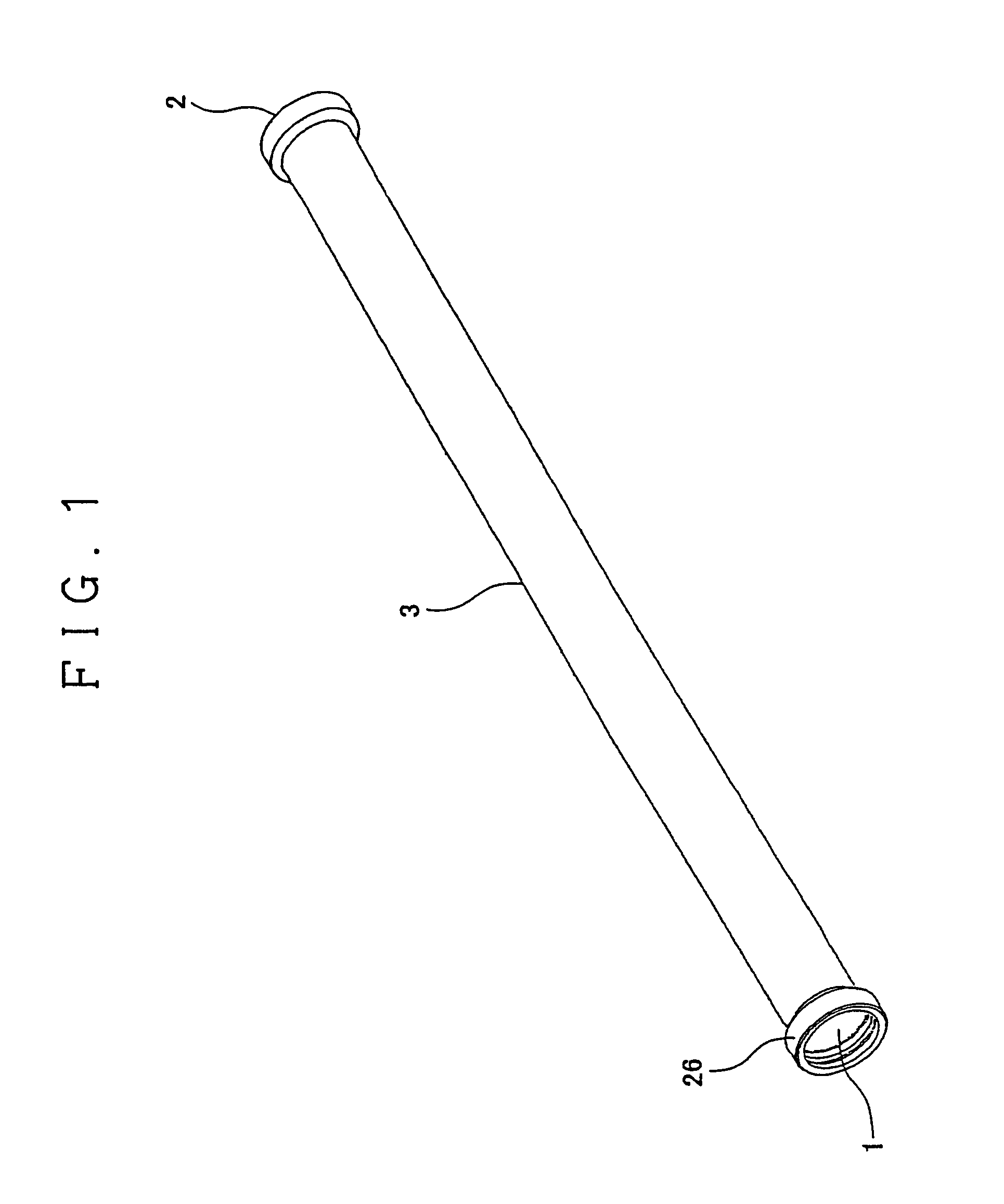
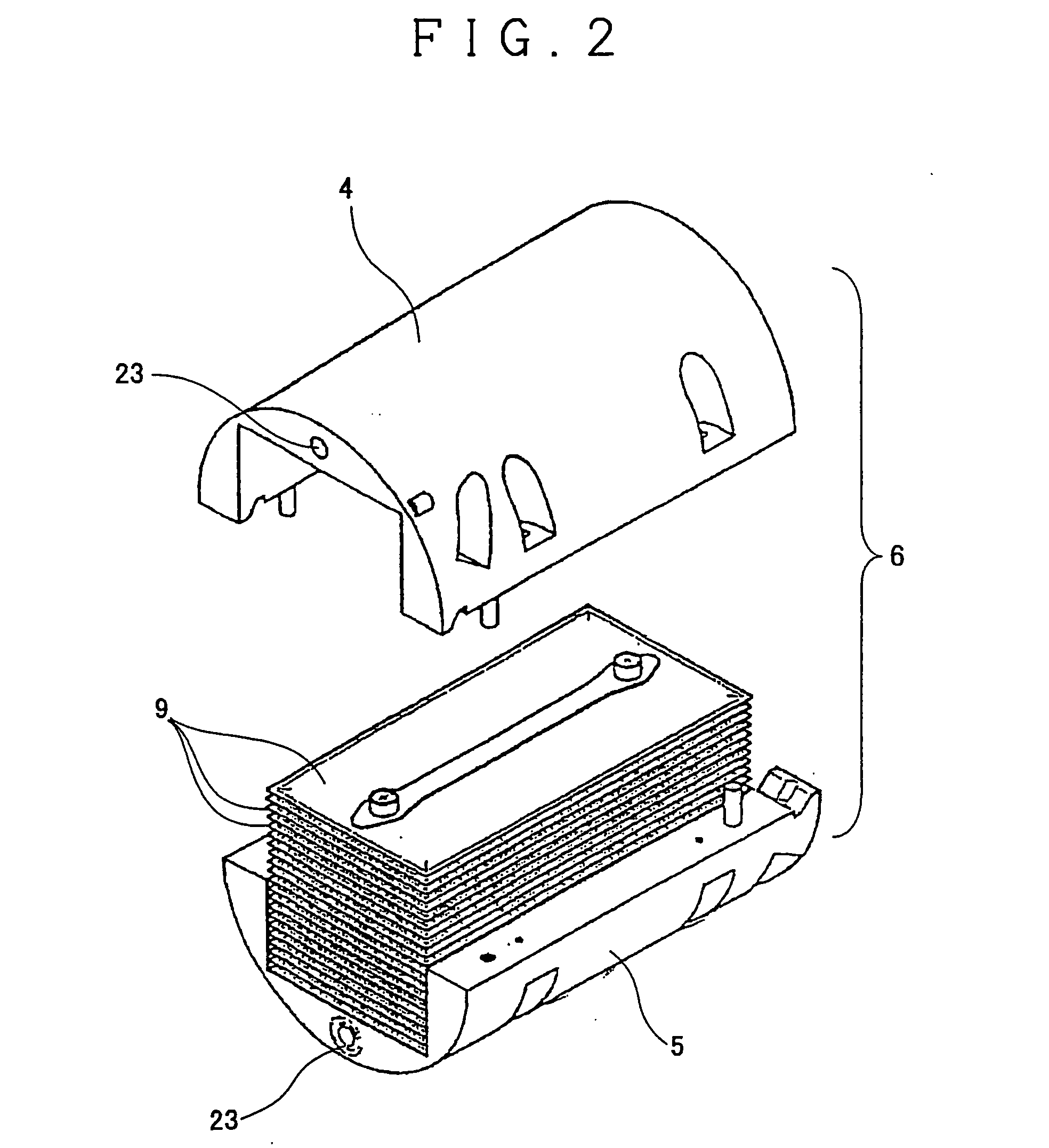
[0058] The examples of the present invention will be described with reference to the attached drawings. FIG. 1 is a perspective view of a pressure vessel 3 having a water inlet 1 at a first end and a concentrate outlet 2 at a second end. As illustrated in FIG. 2, a large number of inner casings 6, each made up of an upper half 4 and a lower half 5, are disposed adjacent to each other along a longitudinal axis of the pressure vessel.

[0059] As illustrated in FIG. 3(a), a flow-regulating plate 7 is mounted on the side of the water inlet 1 of the pressure vessel 3. The flow-regulating plate 7 has plate-like members 8 extending in a circular opening defined on the side of the water inlet 1 of the pressure vessel 3 in a comb-like formation with a certain space between the adjacent plate-like members as aligned in two rows, as illustrated in FIG. 3(b). As illustrated in FIG. 3(d), an enlarged sectional view of the flow-regulating plate 7 as viewed in the direction of arrows D-D in FIG. 3(...


PUM

PropertyMeasurementUnit
Pressureaaaaaaaaaa
Angleaaaaaaaaaa
Flow rateaaaaaaaaaa

Abstract

It is an object of the present invention to provide a membrane separation apparatus and a membrane separation process that are unlikely to cause membrane fouling and plugging, capable of achieving membrane separation even with relatively low flow rate of water, have an excellent membrane packing density, and are unlikely to cause deposition of foreign components in the apparatus. In order to achieve the above object, according to the present invention, vessel-type inner casings are disposed in a pressure vessel along the longitudinal axis thereof, in which the pressure vessel has a water inlet at a first end and a concentrate outlet at a second end. A flow-regulating plate is disposed on the side of the water inlet of the pressure vessel. Stacks of membrane separation units are respectively disposed in the inner casings, and spacers are disposed between the adjacent membrane separation elements. The spacers also serve as sealing members. Each stack of the membrane separation units and the spacers together define a through-hole extending from a first side to a second side, of the stack of the membrane separation elements. The inner casings have permeate discharge passages along the longitudinal axis thereof. The permeate discharge passages are communicated with the through-hole of each stack of the membrane separation elements. Water that has been fed into the pressure vessel via the flow-regulating plate permeates through the membrane separation elements and is discharged to the outside via the through-holes and the permeate discharge passages.

Description

FIELD OF THE INVENTION [0001] The present invention relates to a membrane separation apparatus of a flat sheet membrane type and a membrane separation process that are capable of being utilized in solid-liquid separation, deionization, soluble organic component removal, colloidal silica wastewater treatment, latex wastewater treatment, various waste liquids treatment, tap water filtration, activated sludge treatment, food wastewater treatment, domestic wastewater treatment (water reclamation), ship wastewater treatment, raw sewage treatment, COD reduction, BOD reduction, filter back wash wastewater treatment, printing ink wastewater treatment and the like. BACKGROUND OF THE INVENTION [0002] A membrane separation apparatus is used for separation of liquid (water to be treated), which contains various matters dissolved or mixed in water into purified water (permeate) and highly concentrated water. Of various types of the membrane separation apparatus, a cross-flow membrane separation ...

Claims


Application Information

Patent Timeline
IPC IPC(8): B01D63/08B01D65/00B01D65/02B01D69/06C02F1/44
CPCB01D63/084B01D65/00B01D65/003B01D2319/022C02F1/444B01D2313/04B01D2313/143B01D69/06B01D65/02B01D2313/041
Inventor TANIDA, KATSUYOSHINONAKA, SHINICHISHIMADA, MITSUSHIGEMATSUDA, TSUTOMUHIRAI, KIYOSHIUEMURA, MASAHIROTAKATA, KAZUTAKAITO, YUTAKAHASEGAWA, SUSUMU
Owner KOBELCO ECO-SOLUTIONS CO LTD
Why Eureka
Try Eureka