
Electric actuator

a technology of electric actuators and actuators, applied in the direction of magnets, mechanical equipment, magnetic bodies, etc., can solve the problems of large output, complicated integration operation, and difficulty in using the shifting electric motor b>18, and achieve the effect of swiftly and firmly carrying out the shifting operation

Inactive Publication Date: 2005-06-16
NSK LTD
View PDF13 Cites 3 Cited by
  • Summary
  • Abstract
  • Description
  • Claims
  • Application Information

AI Technical Summary

Benefits of technology

[0022] It is an object of the invention to provide an electric type actuator capable of swiftly and firmly carrying out shifting operation in view of the above-described problem.
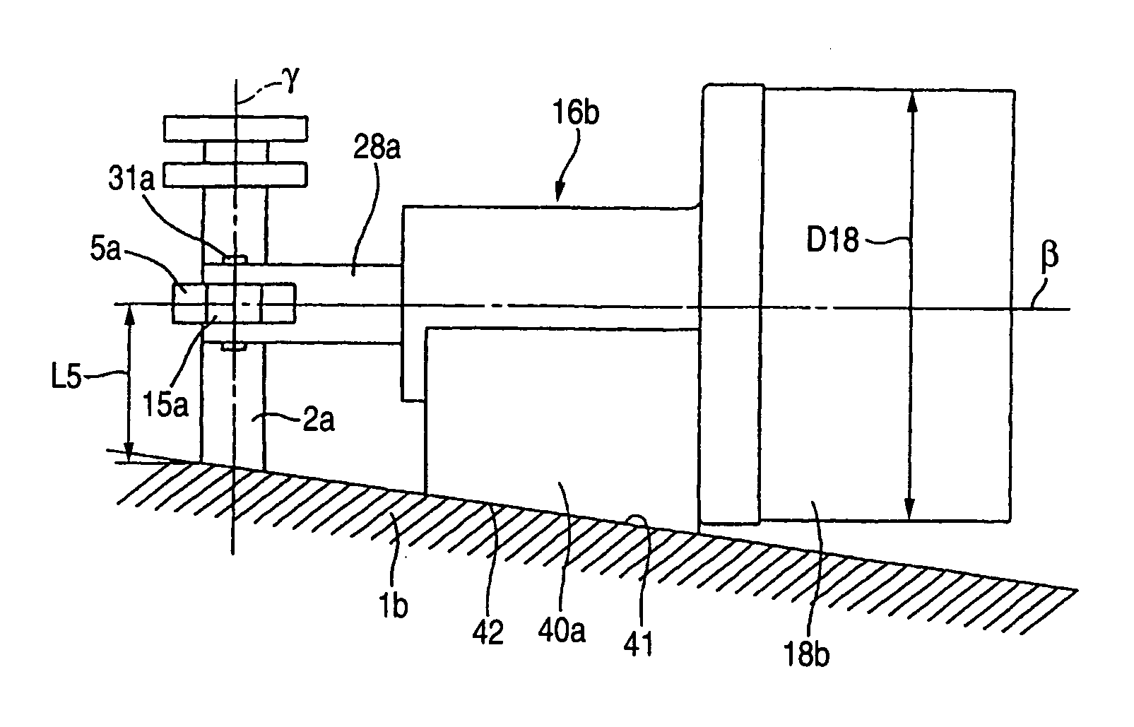
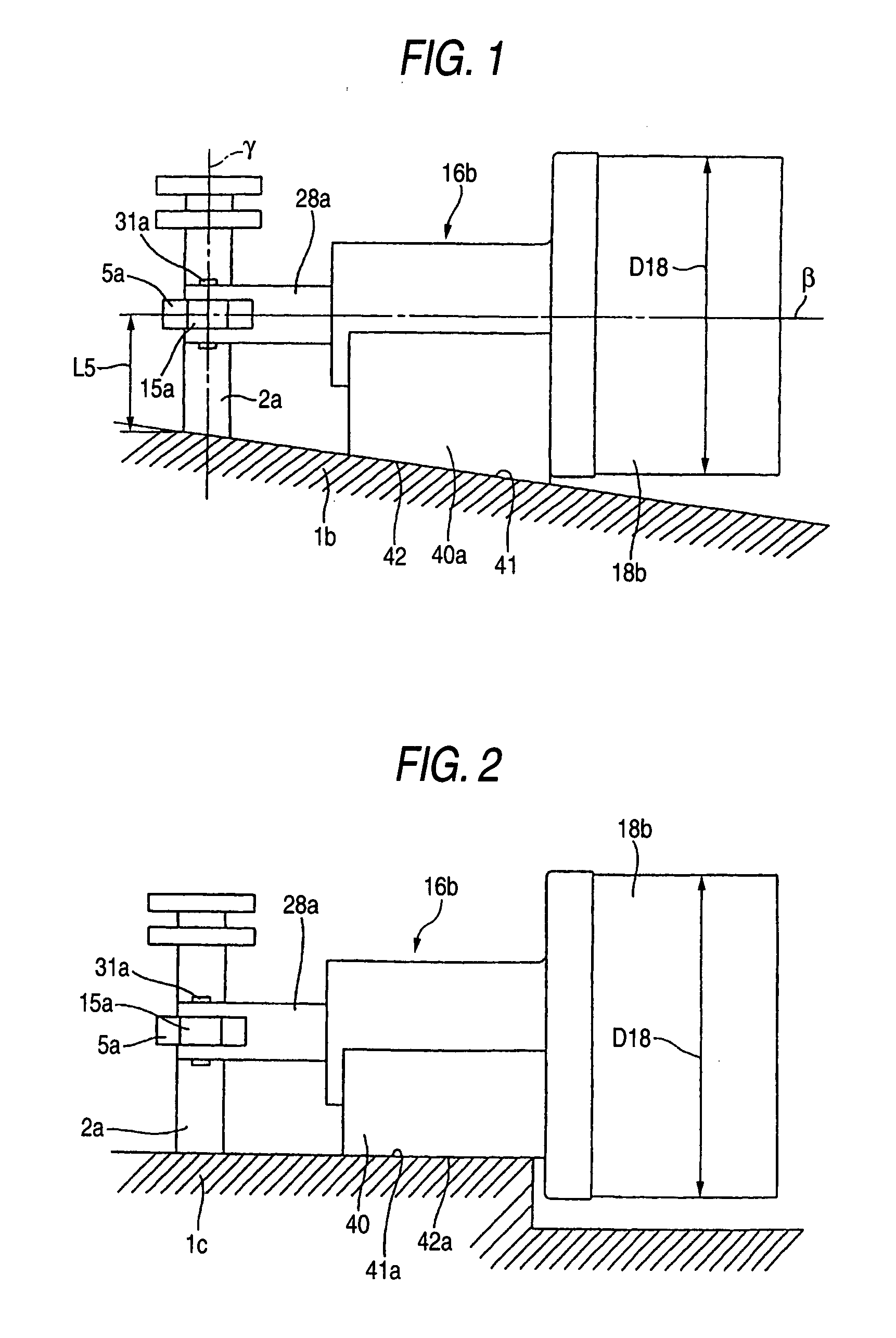
[0030] According to the electric type actuator of the invention constituted as described above, the output of the electric motor can be increased by increasing the outer diameter of the electric motor while ensuring the rigidity of the transmitting member without excessively increasing the amount of projecting the transmitting member from the outer face of the case. Therefore, when the electric type actuator is integrated, for example, an electric driving apparatus for a transmission, gear change operation can swiftly and firmly be carried out.

Problems solved by technology

That is, in the above-described selecting operation and switching operation, a force required for the selecting operation is small, however, a force required for the shifting operation is large and therefore, it is necessary to swiftly and firmly carry out the shifting operation.
However, in the case of the structure of the background art, it is difficult to use the shifting electric motor 18 having the large output.
Further, integrating operation is complicated by providing the above-described bracket.

Method used


Image

  • Electric actuator
  • Electric actuator
  • Electric actuator

Examples


first embodiment

[0058] (First Embodiment)

[0059] An explanation will be given of an electric actuator according to First Embodiment of the invention as follows. FIG. 1 shows a case of applying to attach a shifting actuator 16b integrated to an electric driving apparatus for a transmission for carrying out shifting operation to an outer face of a transmission case 1b according to First Embodiment of the invention. According to the embodiment, the shifting actuator 16b is attached to an outer face 41 of the transmission case 1b containing a gear change unit which is a driven portion at inside thereof. The shifting actuator 16b is made to be able to drive to rotate a switch shaft 2a projected from the outer face of the transmission case 1b per se (a portion integrated with the transmission case 1b). Also in the case of the embodiment, similar to the structure shown in FIGS. 25 and 26, the driving arm 15a is provided at the outer peripheral face of the spline cylinder 5a engaged with the outer periphera...

second embodiment

[0064] (Second Embodiment)

[0065] An explanation will be given of Second Embodiment of the invention as follows. An electric driving apparatus for a transmission according to the embodiment is applicable to the electric driving apparatus for a transmission according to Embodiment 1. An explanation will be given in details in reference to the drawings as follows.

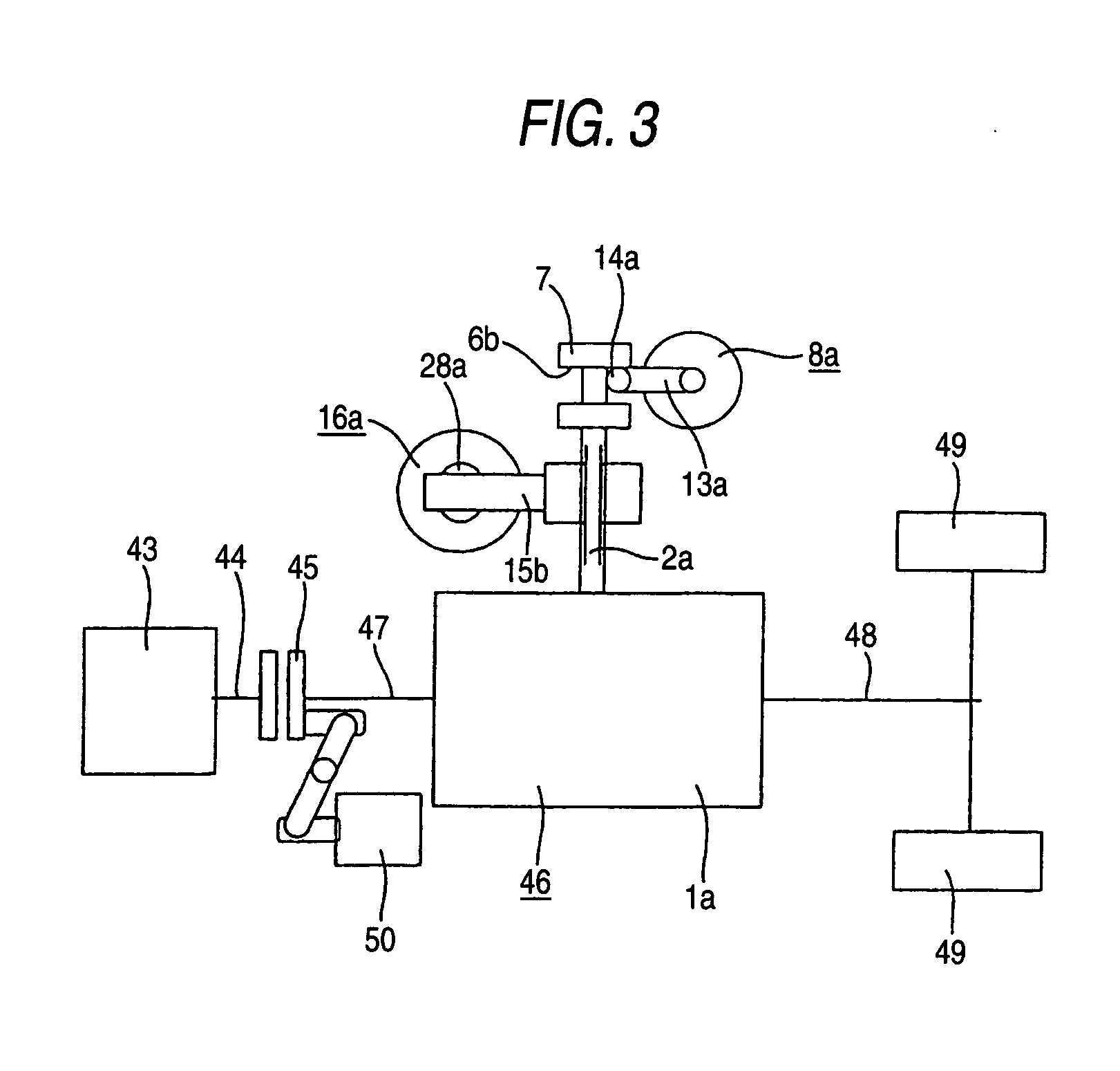
[0066]FIG. 3 shows a transmission apparatus for an automobile integrated with the electric driving apparatus of a transmission according to Second Embodiment of the invention. Rotation of a crankshaft 44 of an engine 43 is transmitted to an input shaft 47 of a gear change unit 46 via a clutch apparatus 45. Further, an output of the gear change unit 46 is transmitted to drive wheels 49, 49 via a propeller shaft 48. In the case of a structure shown in FIG. 3, the clutch apparatus 45 is a dry type single plate clutch combined with a general manual transmission and is connected and disconnected by a clutch actuator 50 of a hydrau...


PUM

PropertyMeasurementUnit
thicknessaaaaaaaaaa
displacementaaaaaaaaaa
radiusaaaaaaaaaa

Abstract

A portion of an outer face 41a installed with a second electric motor 18b is recessed more than a portion of projecting a switch shaft 2a. By the constitution, an outer diameter D18 of the shifting electric motor 18b is increased while ensuring a rigidity of a switch shaft 2a by restraining an amount of projecting the switch shaft 2a. Further, swift and firm gear change operation is made to be able to carry out by increasing an output of the shifting electric motor 18b.

Description

TECHNICAL FIELD [0001] The present invention relates to an electric type actuator for a transmission. BACKGROUND ART [0002] As a transmission for an automobile, there have been widely used a manual transmission in which a driver changes gears by operating a shift lever along with a clutch pedal and an automatic transmission in which a gear ratio is automatically changed in accordance with a driving situation. Further, there is known an automatic transmission there among combined with a torque converter and a planetary gear mechanism, combined with a variable type pulley and an endless belt or the like. Further, in recent years, there has been used a transmission for an automobile for automatically switching a gear change unit which has been used as a manual transmission in a background art and automatically connecting and disconnecting a clutch since operation thereof is easy and a transmission efficiency is higher than that of a general automatic transmission. [0003] International ...

Claims


Application Information

Patent Timeline
Patent Type & Authority Applications(United States)
IPC IPC(8): F16H61/32H02K7/14
CPCH02K7/14F16H61/32
Inventor OTAKI, RYOICHIKAWADA, DAISAKUSUZUKI, HIROSHIHASHITANI, HIDEKI
Owner NSK LTD
Learn More