Method and optical arrangement for beam guiding of a light beam with beam delay

Active Publication Date: 2005-06-16
CARL ZEISS SMT GMBH
View PDF10 Cites 6 Cited by
  • Summary
  • Abstract
  • Description
  • Claims
  • Application Information

AI Technical Summary

Benefits of technology

[0043] It is equally preferred for at least one prism to be used for the at least one expansion optic, since said prism may simultaneously also be used as a beam splitter at the input and/or as a beam combining element at the output of the delay line, as a result of which the number of optical elements can advantageously be reduced.
[0044] Furthermore, the beam guiding optic may preferably have at least one optical element with variable refractive power, which enable a

Problems solved by technology

These high power densities can damage the downstream optical systems or shorten the service life thereof.
In this case, the problem exists that the light beam generated by the light source naturally has a beam divergence, i.e. becomes wider and wider as the path distance increases.
The use of the abovementioned delay lines having an imaging optic that images the input of the delay line onto the output of the delay line has the disadvantage, however, that additional focusing elements are required in the delay line, which constitute an additional cost expenditure.
Furthermore, these imaging optics within the delay line generate intermediate foci which constitute a high radiation burden per

Method used


Image

  • Method and optical arrangement for beam guiding of a light beam with beam delay
  • Method and optical arrangement for beam guiding of a light beam with beam delay
  • Method and optical arrangement for beam guiding of a light beam with beam delay

Examples


Embodiment Construction

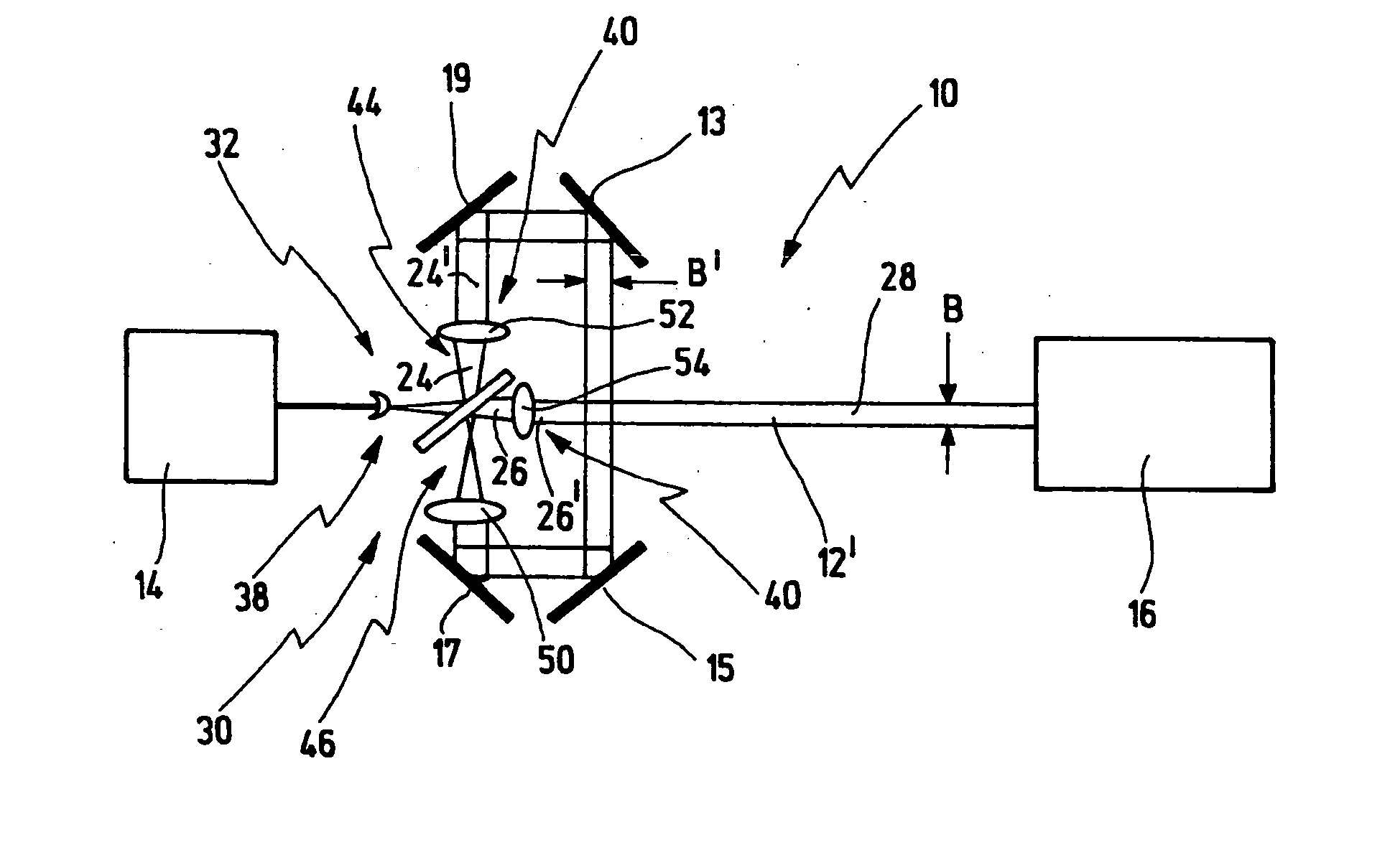
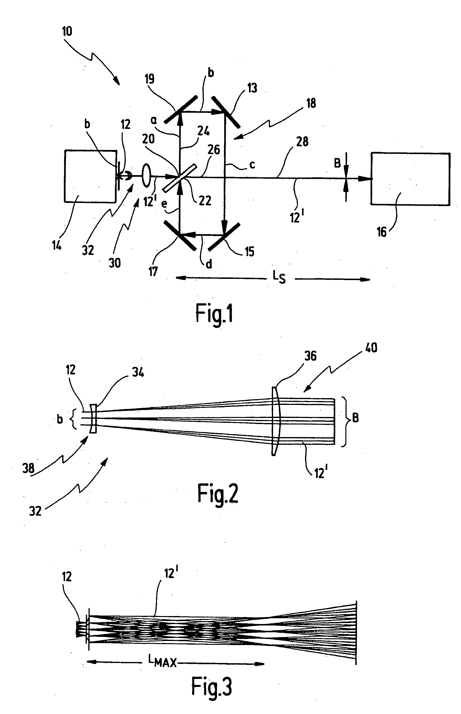
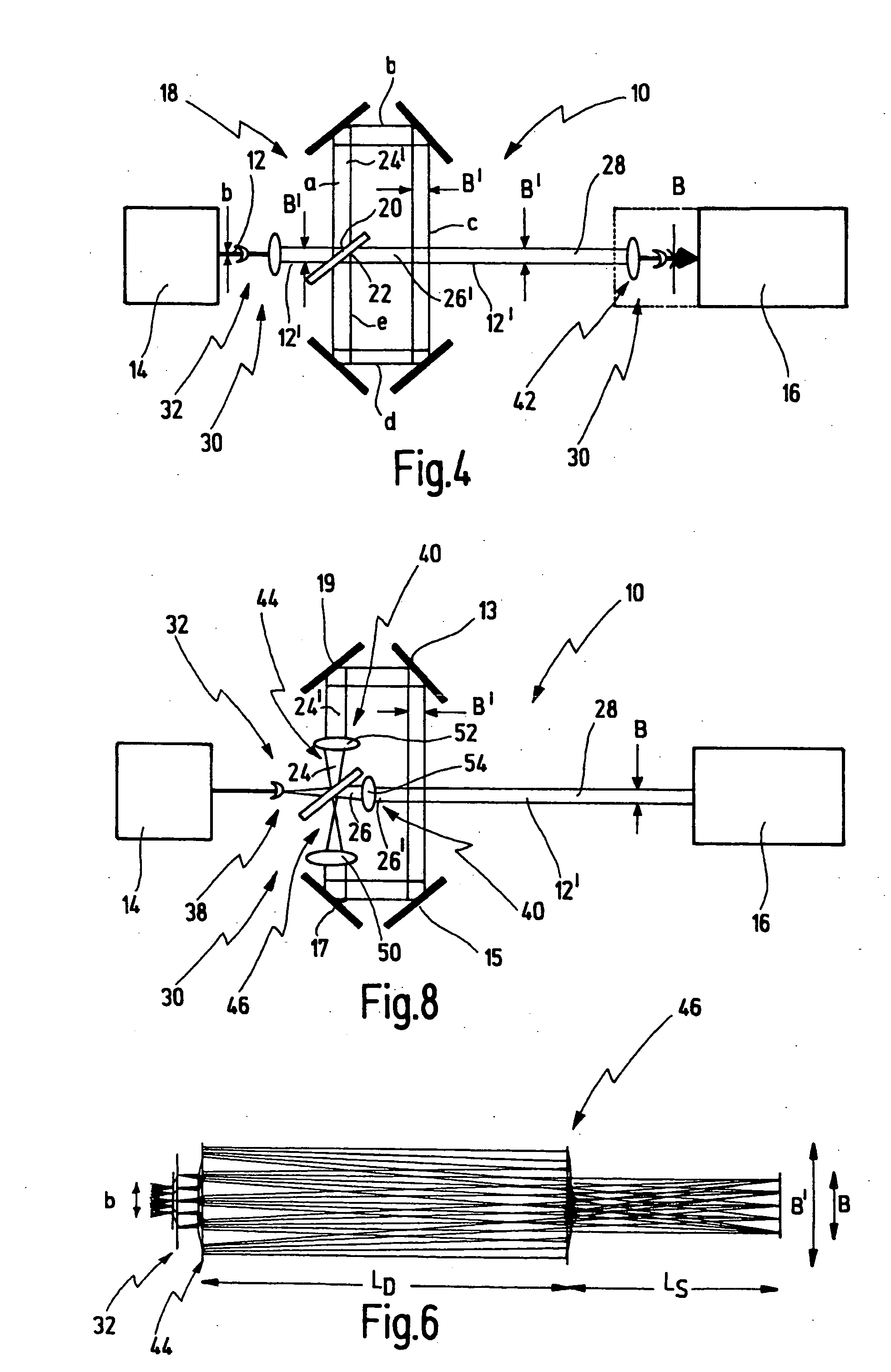
[0057] Firstly, the principle of an optical arrangement for beam guiding of a light beam from a light source to a target location is described with reference to FIGS. 1 to 3. The basic relationships of the beam guiding are elucidated in this case.

[0058]FIG. 1 illustrates an optical arrangement—provided with the general reference symbol 10—for beam guiding of a light beam 12 generated by a light source 14. The optical arrangement 10 has the function of guiding the light beam 12 to a target location 16, and if appropriate shaping said light beam.

[0059] In the case of the preferred use of the optical arrangement 10, the light source 14 is a laser, for example an excimer laser, which generates pulsed laser light, with the result that the light beam 12 is constructed from individual light pulses. In this application, the target location 16 is a projection individual light pulses. In this application, the target location 16 is a projection exposure installation, by way of example, by me...


PUM


Abstract

A method for beam guiding of a light beam generated by a light source to a target location along a path distance LS, comprises splitting the light beam on the path distance LS at least once into a first partial beam and a second partial beam, guiding the first partial beam additionally at least once along a delay line, the first partial beam thereby covering an additional path distance LD, guiding the second partial beam only along the path distance LS, combining the first and second partial beams after the first partial beam having passed through the delay line and guiding the combined beam to the target location, wherein the light beam is guided along the path distance LS and LD in such a way that the light beam generated by the light source has a predetermined beam width B at the target location, expanding the light beam between the light source and the target location at least once to a beam width B′>B and comprising the light beam again at least once in such a way that the light beam has the predetermined beam width B at the target location.

Description

[0001] Applicants claim priority benefits under 35 U.S.C. §119(e) of U.S. Provisional Patent Application Ser. No. 60 / 529,604 filed Dec. 15, 2003.BACKGROUND OF THE INVENTION [0002] The invention relates to a method for beam guiding of a light beam generated by a light source, in particular laser light source, to a target location along a path distance LS. [0003] The invention furthermore relates to an optical arrangement for beam guiding of a light beam generated by a light source, in particular laser light source, to a target location along a path distance LS. [0004] A specific application described in connection with the present invention is the use of the method mentioned in the introduction and of the optical arrangement mentioned in the introduction in semiconductor lithography. [0005] In semiconductor lithography, laser light is used to image a mask onto a wafer by means of a projection exposure installation in order then to fabricate the desired semiconductor components lithog...

Claims


Application Information

Patent Timeline
IPC IPC(8): G02B27/14G03F7/20
CPCG02B27/126G02B27/144G03F7/7055G03F7/70041G02B27/145
Inventor HERKOMMER, ALOISMUENZ, HOLGERSEIFERT, WOLFGANG
Owner CARL ZEISS SMT GMBH
Why Eureka
Try Eureka