
Apparatus for homogeneously distributing lights

a technology for uniform distribution and lights, applied in lighting and heating apparatus, planar/plate-like light guides, instruments, etc., can solve the problems of damage to the quality of images, main bottleneck, and more serious deficiency of black and white stripes shown on the screen, so as to increase the utilization ratio of light sources

Active Publication Date: 2005-06-16
IND TECH RES INST
View PDF5 Cites 6 Cited by
  • Summary
  • Abstract
  • Description
  • Claims
  • Application Information

AI Technical Summary

Benefits of technology

[0011] The primary objective of the present invention is to provide an apparatus for homogeneously distributing lights, which efficiently controls the light emergence direction and homogeneously distributing the lights.
[0012] Another objective of the present invention is to provide an apparatus for homogeneously distributing lights, which improves the light source utilization ratio.
[0013] A further objective of the present invention is to provide an apparatus for homogeneously distributing lights, which applies fewer optical films, and cuts down the manufacture costs.
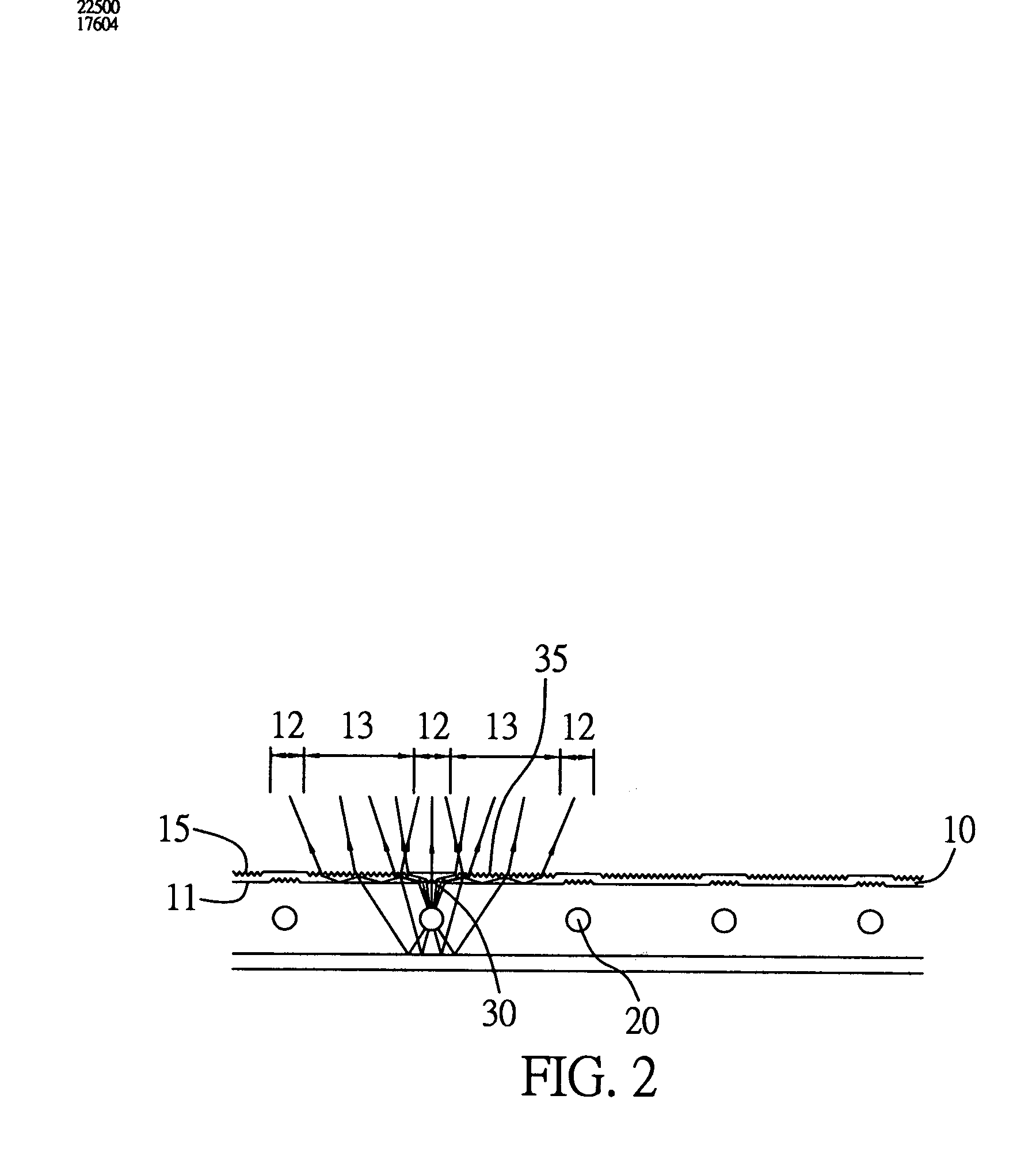
[0017] The emergence microstructure of the emergence surface is designed for damaging total reflection of the lights in the light guide plate, thereby the lights experienced at least one time total reflection pass through the emergence surface where does not correspond to the light source, and emit to the outside environment environment. Thus the directions of the lights passing through the incidence microstructure of the incidence surface are changed, accordingly, the lights are homogeneously distributed, and further the light source utilization ratio is increased.

Problems solved by technology

However, CCFLs are often arranged in a row and disposed at a bottom of an LCD panel, thereby the images displayed on the LCD are asymmetric in light intensity distribution because the diffusion angles of the scattered lights are usually too large, and the light emergence directions are usually disordered.
Thus obvious profiles of the CCFLs are shown on the screen, which damage the quality of the images.
Therefore, under the circumstance of direct type backlight module being applied, the larger of the dimension of the LCD panel and the greater of the number of the CCFLs are used, the more serious of the deficiency of black and white stripes shown on the screen occurs.
The above mentioned problem is a main bottle-neck in the way of the development of the LCD display quality.
However, the above design applies so many optical components as to not easy to be manufactured, and sharply increase the costs.
Furthermore, the effect of homogeneously distributing the lights of the design is finite, and not the best solution to solve the problem.
However, different processes are required in this invention for respectively forming the separate layer 62 and the microstructure layer 63, thereby increasing the manufacture costs.
Furthermore, the processes are complicated and not suitable for mass production, and the effect of homogeneously distributing the lights can not satisfy the images quality requirements of consumers.
However, the backlight module structure 70 comprises so many components that leads to a complicated manufacture process and increases the manufacture costs.
Furthermore, the homogeneous diffusion effect and the efficiency of the light utilization can not satisfy the market demands.
However, the method greatly increases the manufacture costs.
Furthermore, because of the configure limitation, if any one of the CCFLs failures, the whole row of CCFLs will be replaced with a new one.

Method used


Image

  • Apparatus for homogeneously distributing lights
  • Apparatus for homogeneously distributing lights
  • Apparatus for homogeneously distributing lights

Examples


Embodiment Construction

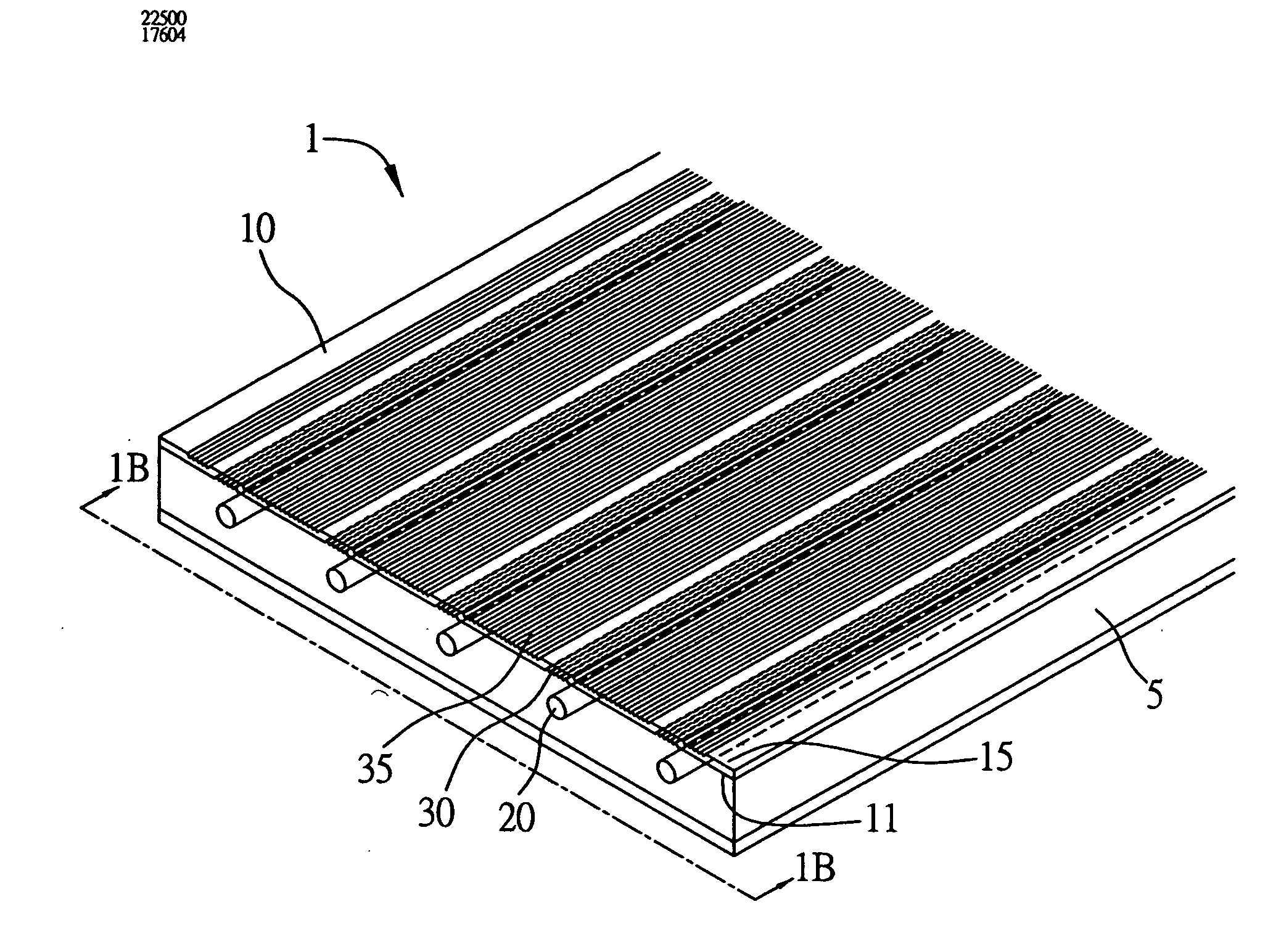
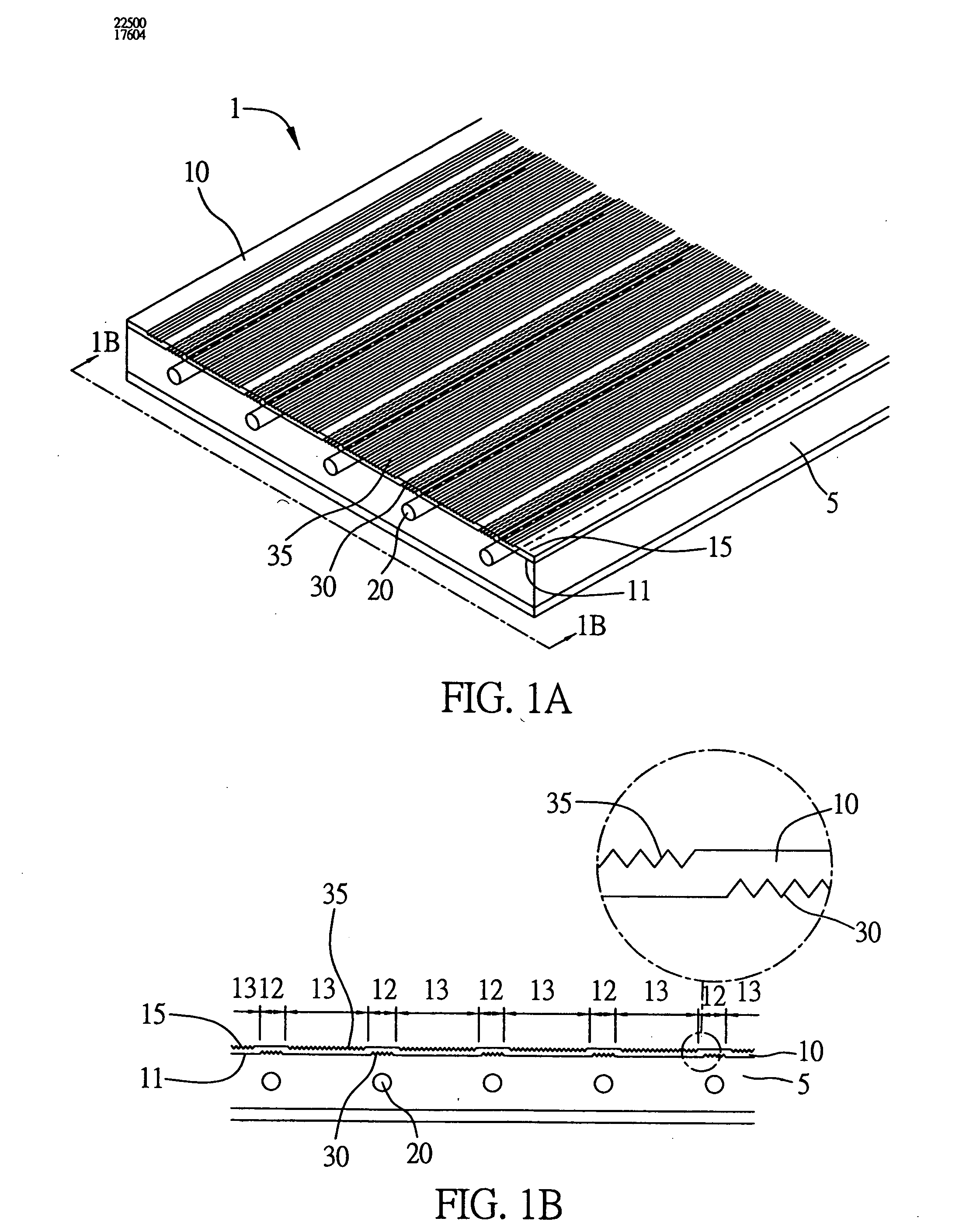
[0027] Embodiments of an apparatus for homogeneously distributing lights 1 (this is referred to simply as “apparatus”) of the present invention will now be explained in detail with reference to the drawings.

[0028] Referring to FIGS. 1A and 1B, schematic views of the apparatus 1 applied in a backlight module in accordance with a preferred embodiment of the present invention are shown, wherein the FIG. 1B is a side view of the FIG. 1A. The apparatus 1 is disposed on a surface of a main body of a backlight module 5. The backlight module 5 comprises a plurality of parallel cold cathode fluorescernt lamps (CCFLs) 20. The apparatus 1 comprises a light guide plate 10. The light guide plate 10 comprises an incidence surface 11 and an emergence surface 15. The incidence surface 11 is arranged opposite to the CCFLs 20. Lights emitted by the CCFLs 20 subsequently pass through the incidence surface 11, the main body of the light guide plate 10 and the emergence surface 15, and then emit to an ...


PUM


Abstract

An apparatus for homogeneously distributing lights includes a light guide plate, an incidence microstructure and an emergence microstructure. The incidence microstructure is arranged on a surface of the light guide plate and opposite to a light source. The emergence microstructure is arranged on a surface of the light guide plate opposite to the incidence microstructure. The lights emitted by the light source pass through said apparatus thereby being homogenously distributed. Thus the manufacture costs are lowered, and the light source utilization ratio is increased.

Description

BACKGROUND OF THE INVENTION [0001] 1. Field of the Invention [0002] The present invention relates generally to an apparatus for homogeneously distributing lights, and more particularly, to an apparatus for homogeneously distributing lights applied to a direct type backlight module. [0003] 2. Description of the Related Art [0004] Large-scale liquid crystal display (LCD) is mainly applied to a notebook computer or an LCD monitor. Liquid crystal material does not emit light itself. Therefore an external light source is needed for displaying images. Because of a trend of light, thin, short and small styles of a light source of a backlight module, and a requirement for being applied to a large-scale panel, such as an LCD television (TV), the backlight module is not only supposed to have the above-mentioned advantages, but also have other advantages, such as high display luminance, broad visual angle, distinct image contrast and long life. Therefore, direct type backlight module, which is...

Claims


Application Information

Patent Timeline
Patent Type & Authority Applications(United States)
IPC IPC(8): F21V8/00
CPCG02B6/0016G02B6/0043G02B6/0036
Inventor PAO, YU-NANLIN, YU-CHENGLIN, TSUNG-HSINLIN, KUEN-LUNG
Owner IND TECH RES INST
Learn More