Pupil color estimating device

a technology of pupil color and estimating device, which is applied in the field of pupil color estimating device, can solve problems such as red-eye phenomenon, pupil or whole pupil, and red capture to be a problem

Active Publication Date: 2005-06-16
ORMON CORP
View PDF4 Cites 82 Cited by
  • Summary
  • Abstract
  • Description
  • Claims
  • Application Information

AI Technical Summary

Benefits of technology

[0054] The present invention can estimate a color of a pupil in which a color contrast is considered for a skin color in an inputted image. Therefore, an origina

Problems solved by technology

Conventionally, a red-eye phenomenon wherein a pupil or whole pupil of the image-captured person is image-captured to be red becomes a problem, regardless of a digital camera or silver-halide camera.
Since the distance between the optical axis of a camera and a flash becomes close to each other recently due to the miniaturization of a camera, the rate of occurrence of the red-eye phenomenon increases, which becomes a problem in particular.
However, when the red eye phenomenon occurs, the red eye is required to be image-corrected, so long as the image cannot be retaken.
However, the image of the pupil having the red-eye phenomenon already occurring loses the original color of the pupil.
Therefore, it is difficult to estimate the original color of the pupil from the image of the pupil having the red-eye phenomenon.
If the original color of the

Method used


Image

  • Pupil color estimating device
  • Pupil color estimating device
  • Pupil color estimating device

Examples


first embodiment

[System Configuration]

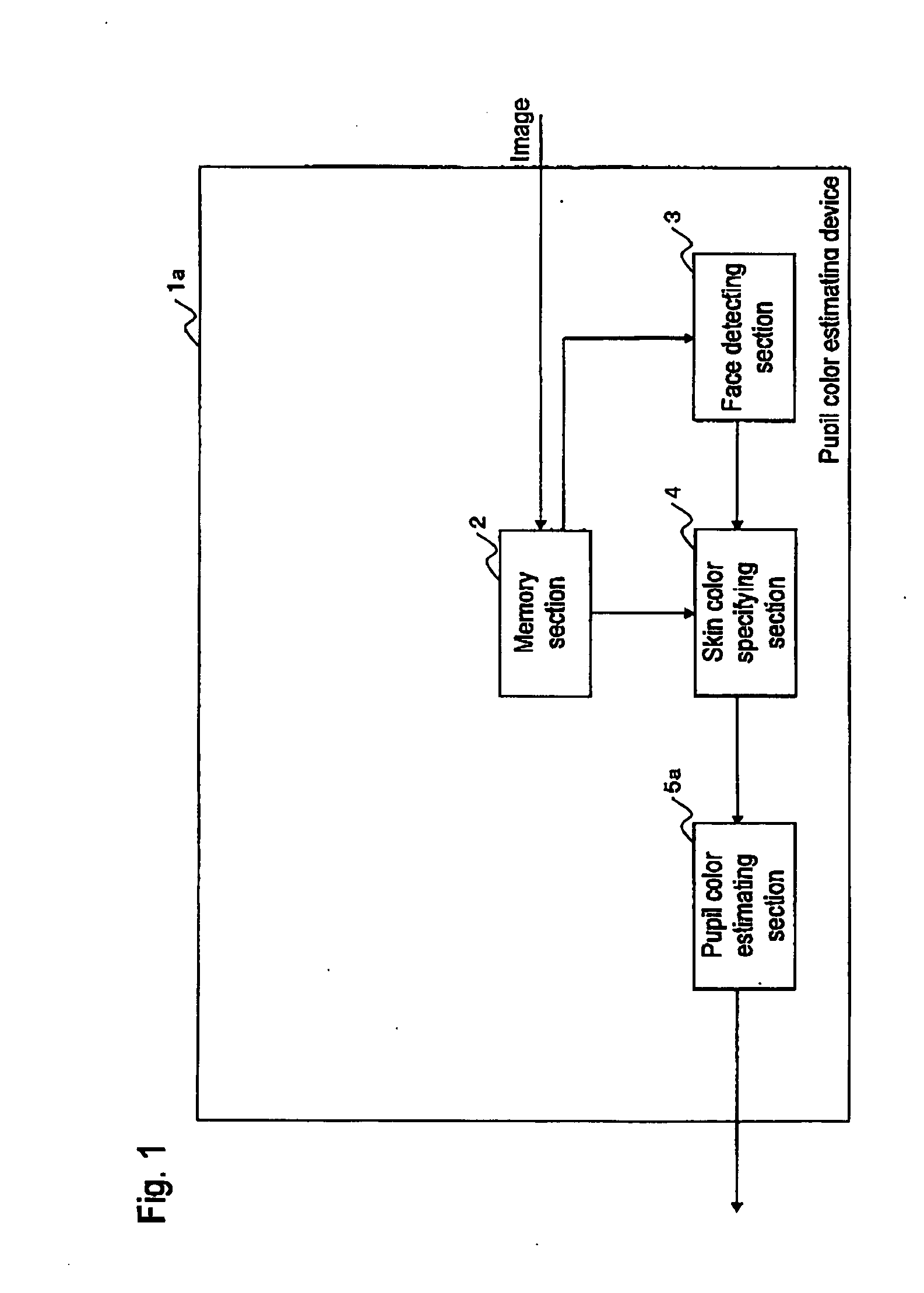
[0071] Firstly explained is a pupil color estimating device 1a that is a first embodiment of the pupil color estimating device. The pupil color estimating device 1a has a CPU (central processing unit), main memory (RAM; Random Access Memory), auxiliary memory or the like, each of which is connected via a bus. The auxiliary memory is configured by using a nonvolatile memory unit. The nonvolatile memory unit here indicates a so-called ROM (Read-Only Memory: including EPROM (Erasable Programmable Read-Only Memory), EEPROM (Electrically Erasable Programmable Read-Only Memory), mask ROM or the like) FRAM (Ferroelectric RAM), hard disk or the like.

[0072]FIG. 1 is a diagram showing a functional block of the pupil color estimating device 1a. Various programs (OS, application, or the like) stored in the auxiliary memory is loaded to the main memory to be executed by the CPU, whereby the pupil color estimating device 1a functions as a device including a memory section ...

second embodiment

[System Configuration]

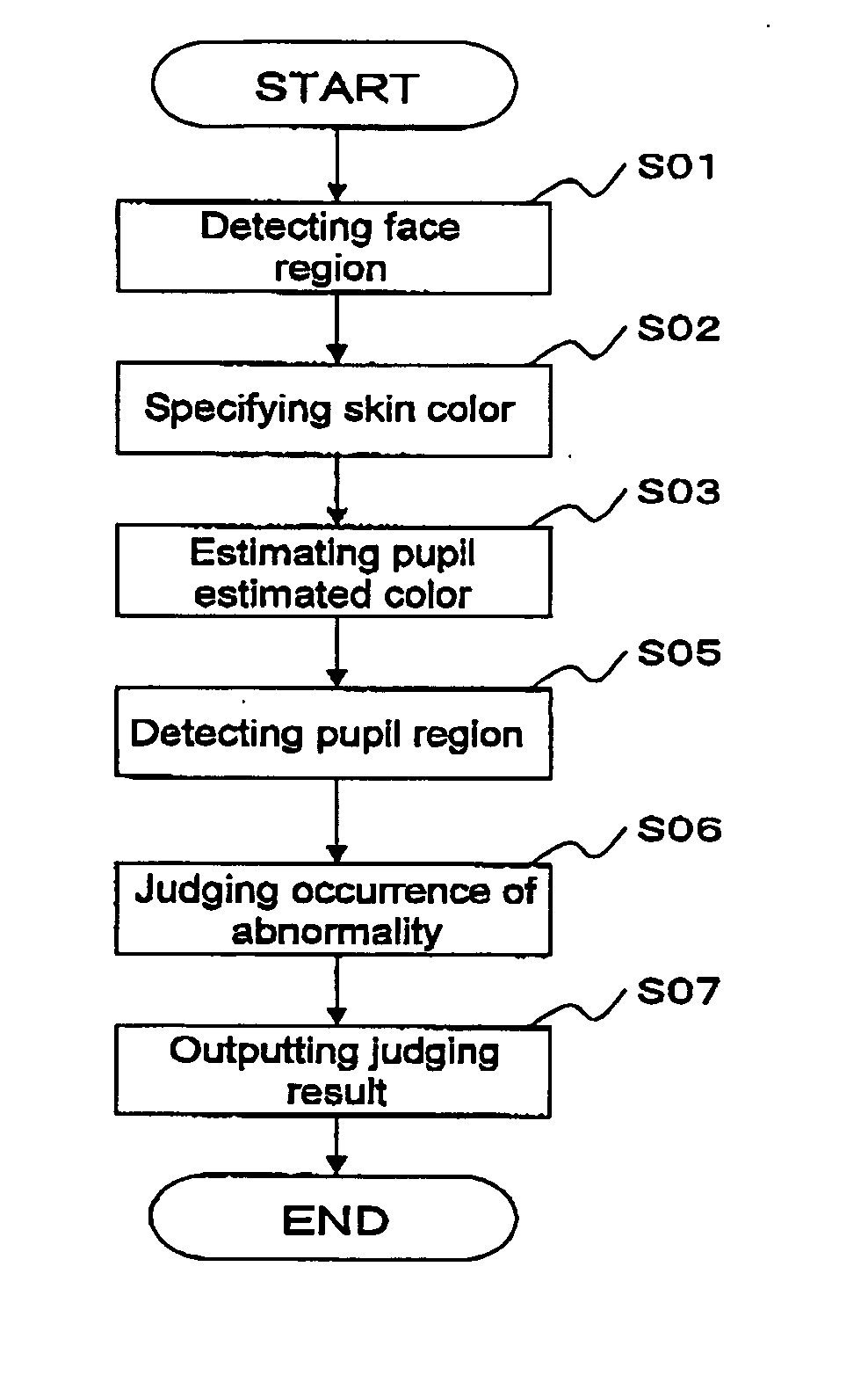
[0094] Subsequently explained is a pupil color estimating device 1b that is the second embodiment of the pupil color estimating device. FIG. 5 is a view showing an example of a functional block of the pupil color estimating device 1b. The pupil color estimating device 1b is different from the pupil color estimating device 1a in that it is further provided with a pupil detecting section 7 and a judging section 8. The different points of the pupil color estimating device 1b from the pupil color estimating device 1a will be explained hereinbelow. It should be noted that the pupil detecting section 7 and the judging section 8 are realized in such a manner that a program is executed by a CPU. Further, each of the pupil detecting section 7 and the judging section 8 may be configured as a dedicated chip. Moreover, each processing section may be mounted as a hybrid of a hardware and a software.

[Pupil Detecting Section]

[0095] The pupil detecting section 7 executes a ...

third embodiment

[System Configuration]

[0108] Subsequently explained is a pupil color estimating device 1c that is the third embodiment of the pupil color estimating device. FIG. 7 is a view showing an example of a functional block of the pupil color estimating device 1c. The pupil color estimating device 1c is different from the pupil color estimating device 1b in that it is further provided with a correcting section 9. The different points of the pupil color estimating device 1c from the pupil color estimating device 1b will be explained hereinbelow. It should be noted that the correcting section 9 is realized in such a manner that a program is executed by a CPU. Further, the correcting section 9 may be configured as a dedicated chip. Moreover, each processing section may be mounted as a hybrid of a hardware and a software.

[Correcting Section]

[0109] The correcting section 9 executes a correcting process based upon the judging result by the judging section 8. Specifically, the correcting section...


PUM


Abstract

An original pupil color of a subject person in an image in which an abnormality such as a red-eye or gold-eye occurs is estimated. Further, whether an image correction is required or not and to produce an image having a natural pupil color in the image correction by estimating the original pupil color from the image is judged. A pupil color estimating device has a skin color of a subject person specified from an inputted image, regardless of whether an abnormality such as a red-eye or gold-eye occurs. This skin color is substituted in an approximate equation based upon a statistical result carried out in advance, and thereby a normal color component of a pupil is estimated from the skin color of the subject person.

Description

BACKGROUND OF THE INVENTION [0001] 1. Field of the Invention [0002] The present invention relates to a technique that is effective when it is applied to an imaging device for image-capturing an image (particularly, an image in which a person's face is image-captured), an information processing device or an output device that handles an image, a software or the like. [0003] 2. Description of the Related Art [0004] Conventionally, a red-eye phenomenon wherein a pupil or whole pupil of the image-captured person is image-captured to be red becomes a problem, regardless of a digital camera or silver-halide camera. As a similar problem, there is gold-eye phenomenon in which a pupil or whole pupil of a person is image-captured to be gold. The red-eye or gold-eye phenomenon described above (hereinafter, the explanation is made by taking the red-eye phenomenon as an example) is a phenomenon caused such that flash light incident on a bulb of an eye from a pupil region is reflected on the reti...

Claims


Application Information

Patent Timeline
IPC IPC(8): G03B27/73G06T1/00G06T7/00G06T7/40H04N5/232
CPCG06T2207/30216G06T7/408G06T7/90
Inventor KAKIUCHI, TAKASHISENGA, MASAHIROHOSOI, SATOSHIMATSUOKA, MIKI
Owner ORMON CORP
Why Eureka
Try Eureka