Load lock and load lock chamber using the same

Inactive Publication Date: 2005-06-16
JUSUNG ENG
View PDF11 Cites 51 Cited by
  • Summary
  • Abstract
  • Description
  • Claims
  • Application Information

AI Technical Summary

Benefits of technology

[0009] Accordingly, the present invention is conceived to solve the above problems in the prior art. An object of the present invention is to provide a load lock and a load lock chamber using the same, capabl

Problems solved by technology

Further, as the space in the chamber increases, it takes a longer time to

Method used


Image

  • Load lock and load lock chamber using the same
  • Load lock and load lock chamber using the same
  • Load lock and load lock chamber using the same

Examples


Example

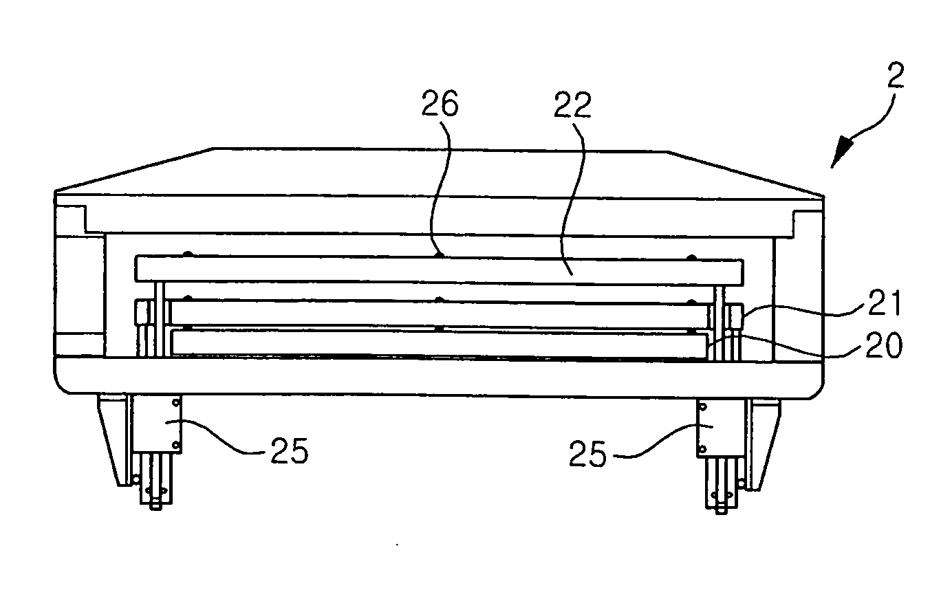
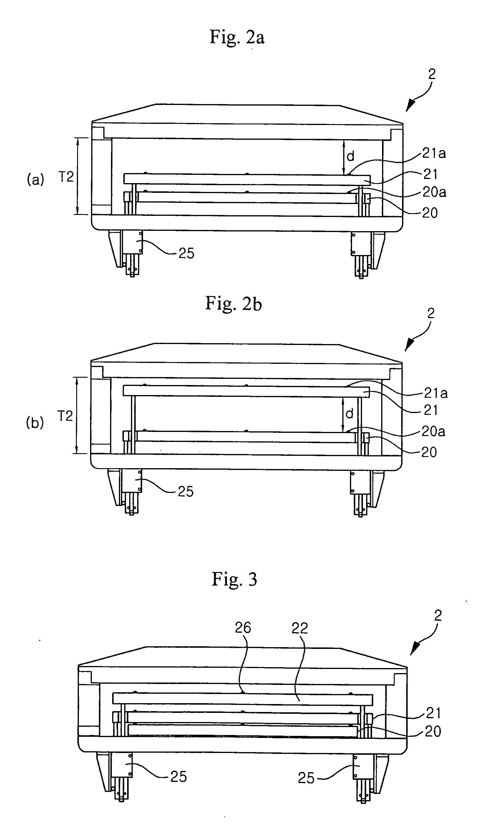
[0036] The preferred embodiments of the present invention will be described below in detail with reference to the accompanying drawings. However, the invention is not intended to be limited to the following embodiments and various changes and modifications may be made within the scope of the invention defined by the claims. The preferred embodiments are included merely to aid in the understanding of the invention. The same reference numerals are used throughout the different drawings to designate the same or similar components.

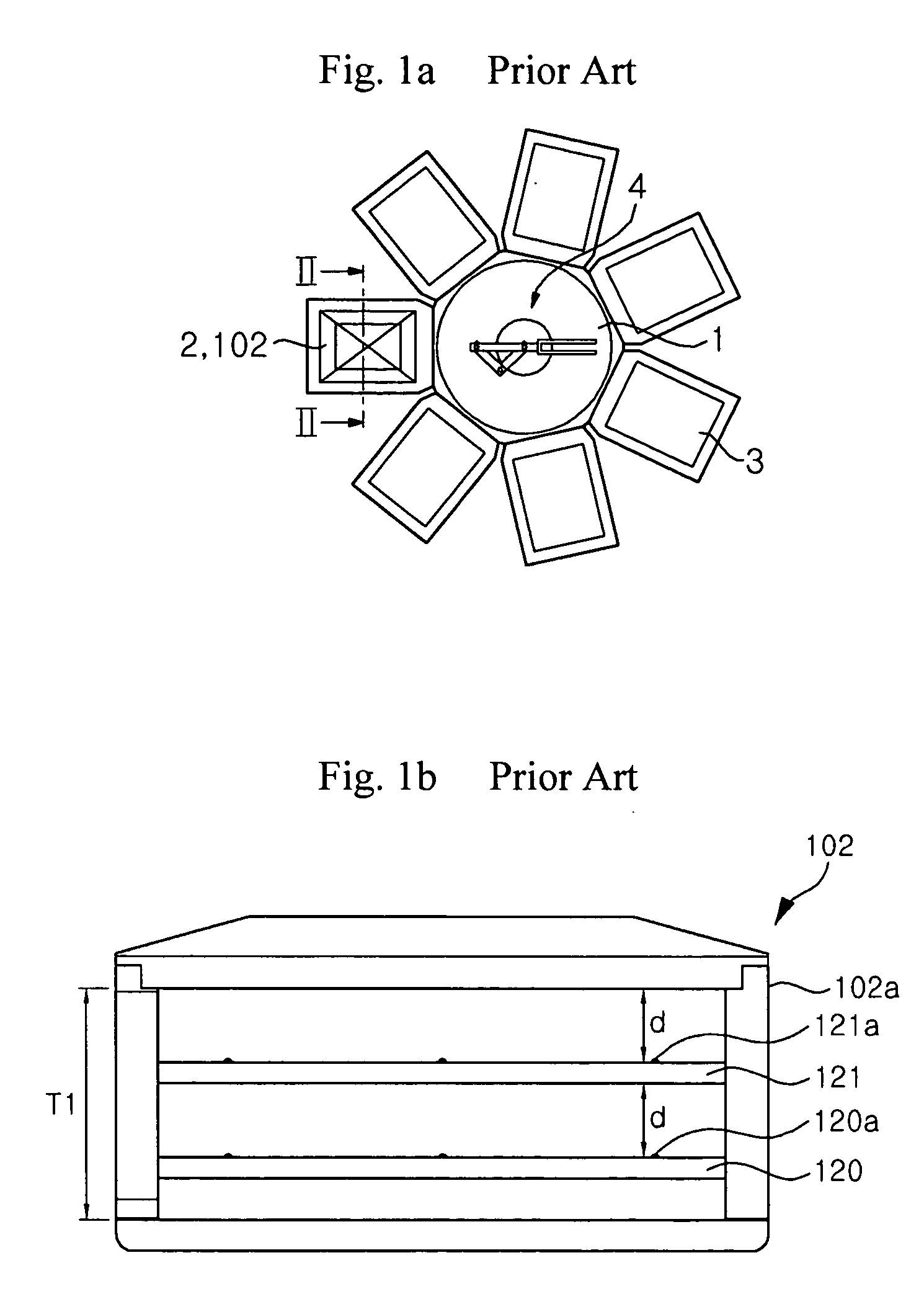
[0037] A substrate processing apparatus including a load lock chamber according to the present invention has the same construction as that of FIG. 1a. Similarly, a transfer unit 4 is provided at a center of a transfer chamber 1 which is coupled ounted to a sidewall of the load lock chamber 2. By an arm coupled to the transfer unit 4, a substrate loaded on a substrate support panel provided in the load lock chamber is transferred to a process chamber, or the s...


PUM


Abstract

Disclosed herein is a load lock to be on standby after loading a plurality of substrates in cooperation with a transfer means adapted to transfer the substrates from process chambers in turn. The present invention provides the load lock which increases the transfer rate thereof to efficiently transfer the substrates to the process chambers or the exterior, and a load lock chamber using the load lock. According to the present invention, the load lock includes a plurality of substrate support panels which support the substrates thereon, are movable vertically, and are spaced apart from each other by a distance that is greater than the thickness of the substrate, and drive units for vertically moving at least one of the substrate support panels.

Description

[0001] This application claims the priority of Korean Patent Application No. 2003-79888, filed on Nov. 12, 2003, in the Korean Intellectual Property Office, the disclosure of which is incorporated herein in its entirety by reference. BACKGROUND OF THE INVENTION [0002] 1. Field of the Invention [0003] The present invention relates generally to a load lock to load or unload a plurality of substrates onto or from a process chamber in cooperation with a transfer means adapted to transfer a substrate, such as a semiconductor, a liquid crystal display (LCD), or an organic light emitting display (OLED), and more particularly, to a load lock and a load lock chamber using the same, capable of increasing a substrate transfer rate, and efficiently transferring substrates to a process chamber. [0004] 2. Description of the Related Art [0005]FIG. 1a is a schematic plan view of a general multi-chamber-type substrate processing apparatus including a load lock. The apparatus includes a transfer cham...

Claims


Application Information

Patent Timeline
IPC IPC(8): B65G1/00B65G49/05G03F7/00H01L21/677H01L21/68
CPCH01L21/67739H01L21/67748H01L21/67751
Inventor QUAN, YONGKO, BUCHOI, JAE
Owner JUSUNG ENG
Why Eureka
Try Eureka