Solution spray apparatus and solution spray method
a technology of spraying apparatus and spraying solution, which is applied in the direction of coating, fishing, other angling devices, etc., can solve the problems of low productivity, degrade image quality, and low productivity, and achieve the effect of quick control and quick
- Summary
- Abstract
- Description
- Claims
- Application Information
AI Technical Summary
Benefits of technology
Problems solved by technology
Method used
Image
Examples
first embodiment
(First Embodiment)
[0075] The first embodiment of the present invention will be described below with reference to several views of the accompanying drawing.
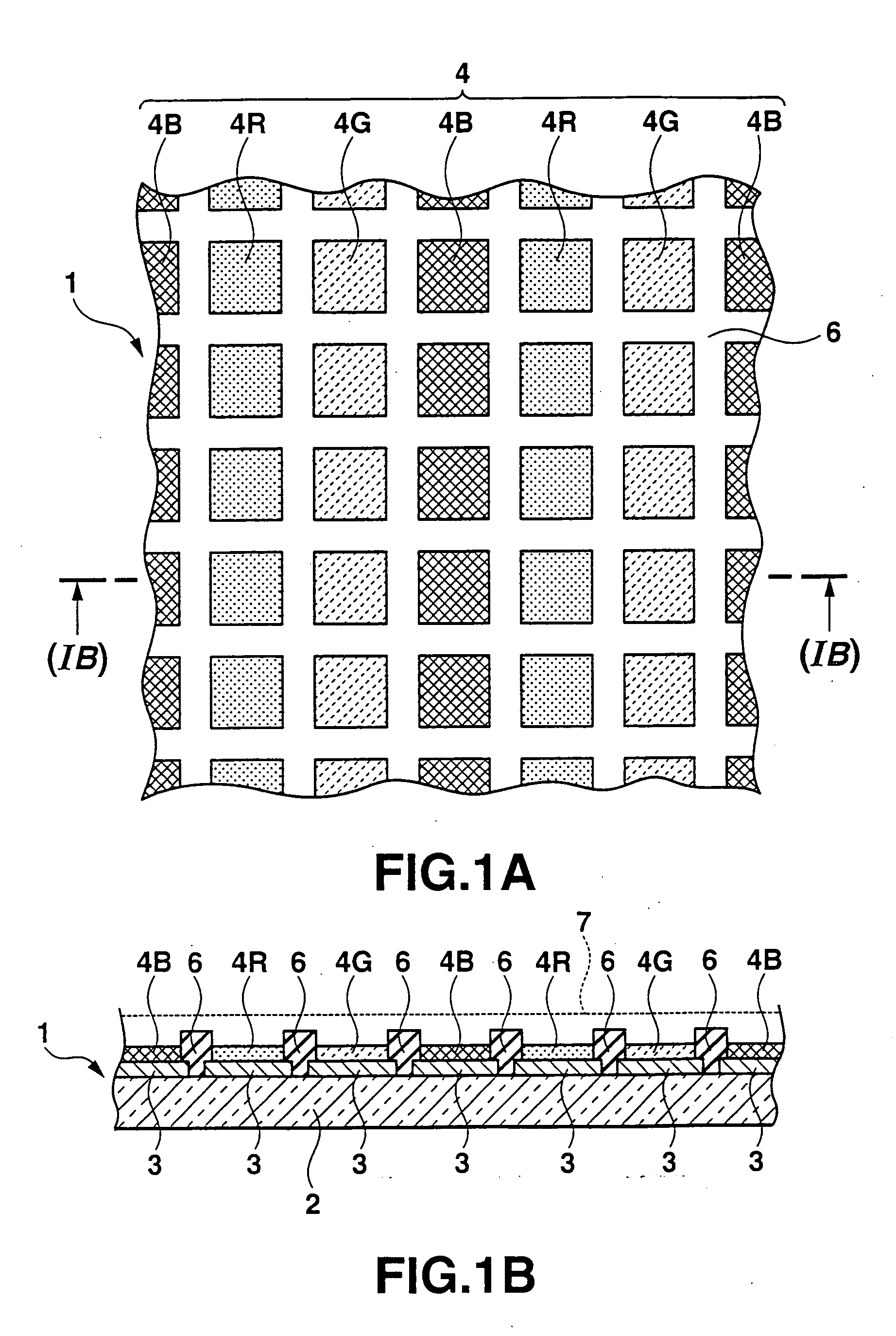
[0076]FIG. 1A is a plan view showing an organic EL display panel 1. FIG. 1B is a sectional view taken along the line (IB)-(IB) inFIG. 1A.
[0077] The organic EL display panel 1 comprises a transparent substrate 2 on which a plurality of pixels are formed. An organic EL element is formed-in each pixel. An example of the transparent substrate 2 is a glass substrate such as a silica glass substrate or borosilicate glass-substrate.
[0078] A plurality of transparent electrodes 3 are arrayed and formed in a matrix on one or upper surface of the transparent substrate 2. The transparent electrode 3 has a relatively high work function, and serves as the anode electrode of the organic EL element. The transparent electrode 3 is formed form a conductive, light-transmitting material. The transparent electrode 3 is formed from at least one mate...
second embodiment
(Second Embodiment)
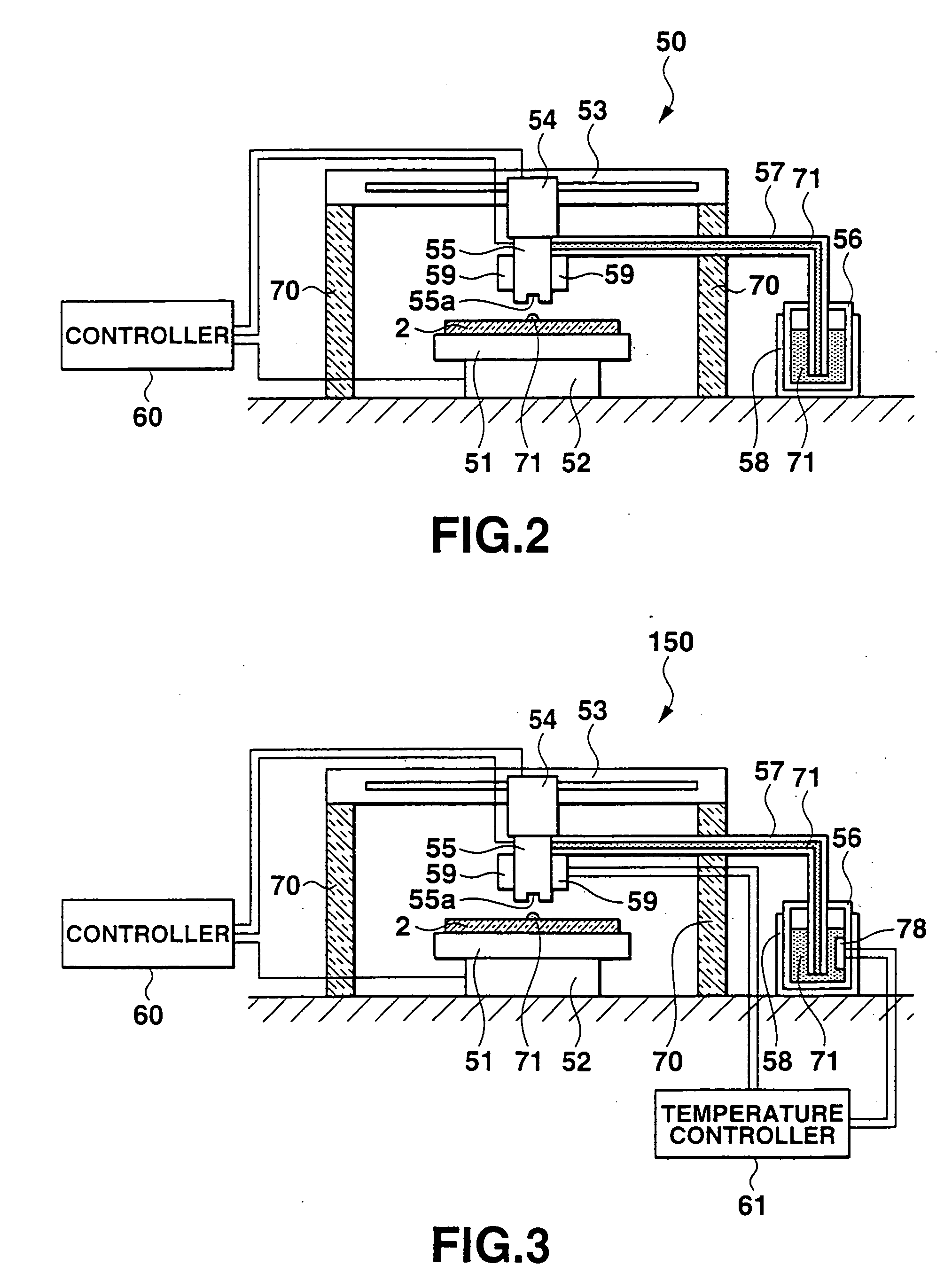
[0117] A solution spray apparatus 150 as shown in FIG. 3 may be used as an apparatus which forms an organic EL layer 4. The same reference numerals as those of the building components of the solution spray apparatus 50 denote the same building components of the solution spray apparatus 150, and a detailed description thereof will be omitted.
[0118] The solution spray apparatus 150 comprises a temperature controller 61 in addition to the arrangement of the solution spray apparatus 50 shown in FIG. 2. The temperature controller 61 controls heating by first and second heat-insulating units 58 and 59. More specifically, an organic material solution tank 56 incorporates a temperature measurement unit (thermometer) 78 which measures the temperature of an EL solution 71. The measured temperature is fed back from the temperature measurement unit 78 to the temperature controller 61. The temperature controller 61 controls the first heat-insulating unit 58 so as to keep the ...
third embodiment
(Third Embodiment)
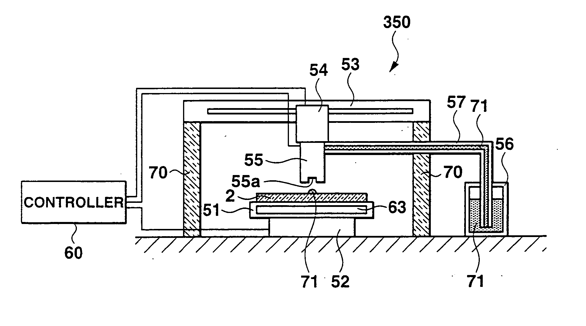
[0120] A solution spray apparatus 250 as shown in FIG. 4 may be used as an apparatus which forms an organic EL layer 4. The same reference numerals as those of the building components of the solution spray apparatus 50 denote the same building components of the solution spray apparatus 250, and a detailed description thereof will be omitted.
[0121] The solution spray apparatus 150 comprises a heat insulator 62 in addition to the arrangement of the solution spray apparatus 50 shown in FIG. 2. The heat insulator 62 is interposed between a head 54 and nozzle or nozzles 55 so as to be sandwiched between them. The heat insulator 62 prevents conduction of the heat of the nozzle 55 heated by first and second heat-insulating units 58 and 59 to the head 54. If the head 54 is heated, it expands and cannot be positioned at high precision, and the droplet landing position may deviate. However, in the solution spray apparatus 250, the heat insulator 62 suppresses heating of the...
PUM
| Property | Measurement | Unit |
|---|---|---|
| distance | aaaaa | aaaaa |
| temperature | aaaaa | aaaaa |
| temperature | aaaaa | aaaaa |
Abstract
Description
Claims
Application Information
 - R&D
- Intellectual Property
- Life Sciences
- Materials
- Tech Scout
- Unparalleled Data Quality
- Higher Quality Content
- 60% Fewer Hallucinations
Browse by: Latest US Patents, China's latest patents, Technical Efficacy Thesaurus, Application Domain, Technology Topic, Popular Technical Reports.
© 2025 PatSnap. All rights reserved.Legal|Privacy policy|Modern Slavery Act Transparency Statement|Sitemap|About US| Contact US: help@patsnap.com


