Power amplifier input structure having a differential output

a power amplifier and input structure technology, applied in the direction of amplifiers with semiconductor devices only, dc-amplifiers with dc-coupled stages, amplifiers with semiconductor devices, etc., can solve the problems of variable input impedance, input impedance, change, etc., and achieve the effect of reducing the difficulty of transmitting vco driving the power amplifier

Active Publication Date: 2005-06-23
QUALCOMM INC
View PDF27 Cites 17 Cited by
  • Summary
  • Abstract
  • Description
  • Claims
  • Application Information

AI Technical Summary

Problems solved by technology

In some applications of power amplifiers, various problems are encountered.
In prior art RF power amplifiers, another common problem is that the input impedance, as seen at the RF input terminal, changes as the output power of the power amplifier varies.
This problem of a varying input impedance can cause difficulties with the transmit VCO driving the power amplifier, such as a variation in the output frequency of the VCO.
Also, this problem causes difficulties with the ability to use different transmit VCO modules with a power amplifier.

Method used


Image

  • Power amplifier input structure having a differential output
  • Power amplifier input structure having a differential output
  • Power amplifier input structure having a differential output

Examples


Embodiment Construction

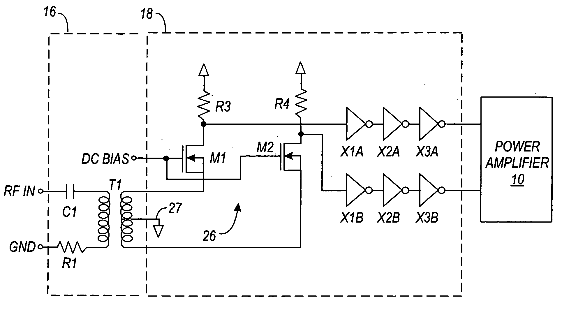
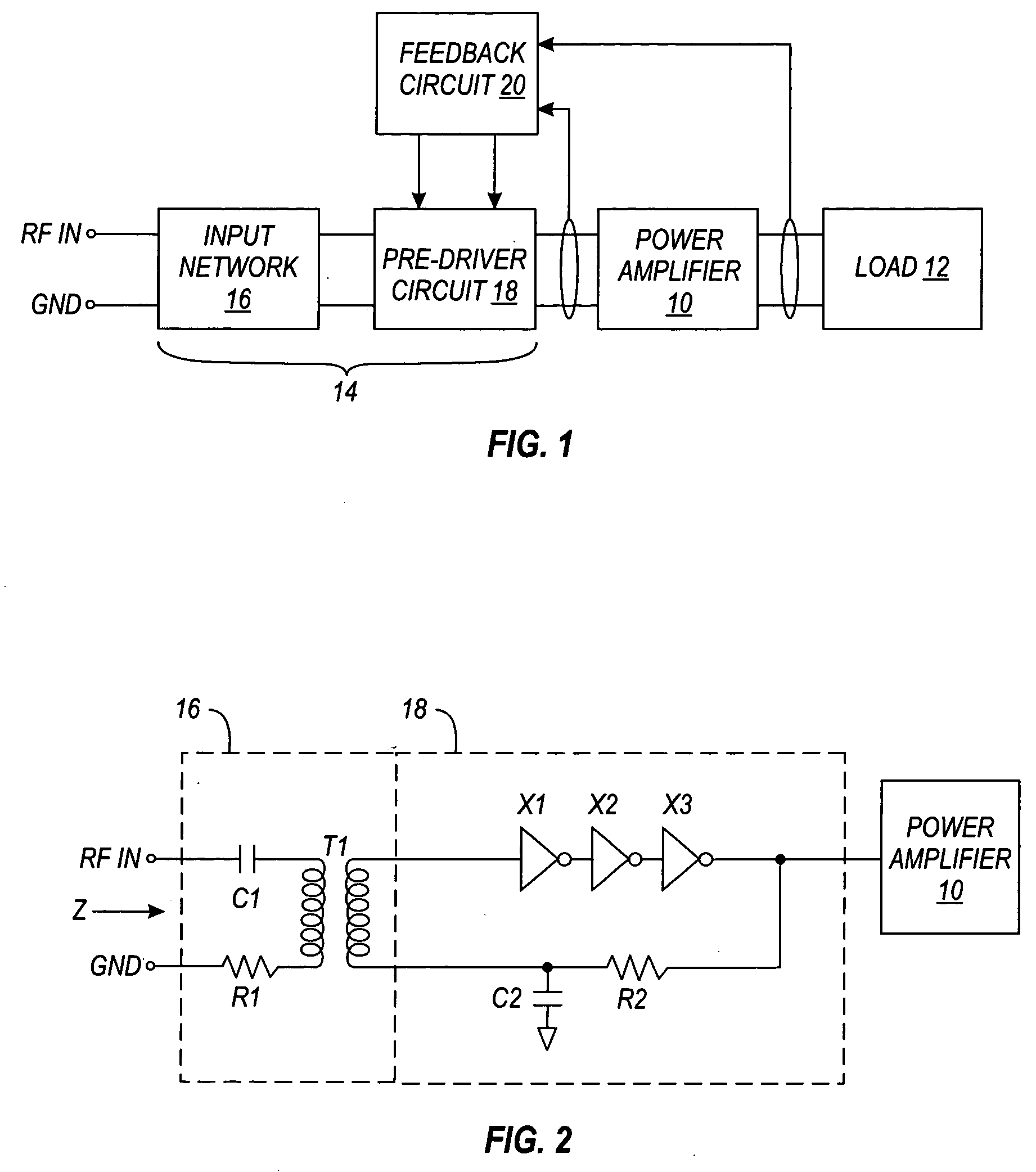
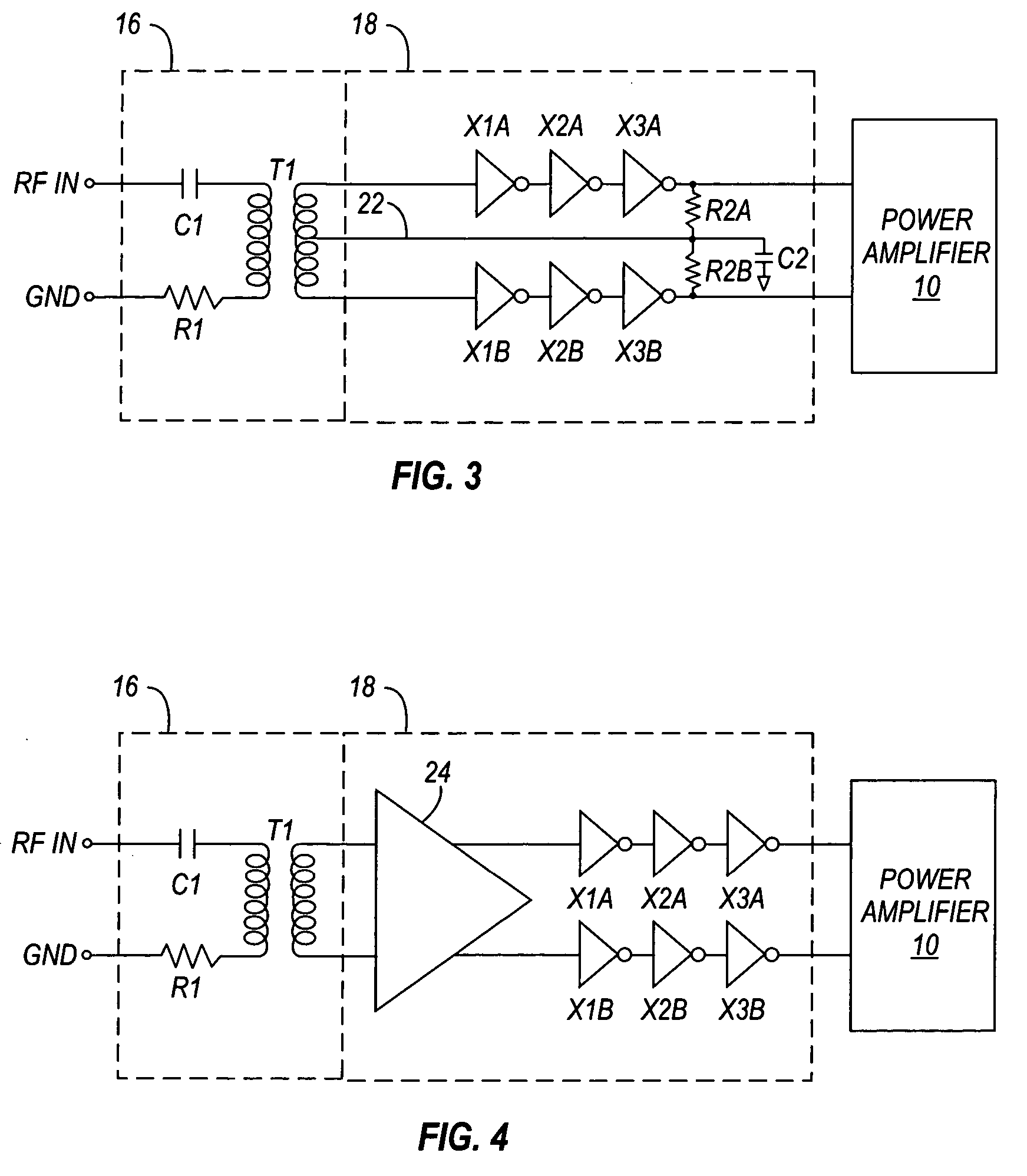
[0020] In order to provide a context for understanding this description, the following description illustrates one example of a typical application of the present invention. A power amplifier using the input structure of the present invention may be used with a wireless transmission system such as a cellular or mobile telephone or other device. In a wireless device such as a cellular telephone, the wireless device may include a transceiver, an antenna duplexer, and an antenna. Connected between the transceiver and the antenna duplexer is an RF power amplifier for amplifying signals for transmission via the antenna. In the case of a wireless telephone application, the invention may be applied to GSM, CDMA, PCS, DCS, etc., or any other wireless systems. This is just one example of an application of a power amplifier utilizing the present invention. The invention may also be used in any other application requiring a power amplifier.

[0021] Generally, the present invention provides an i...


PUM


Abstract

A method and apparatus provides an input structure for a power amplifier. In one example, the input structure has an input network and a predriver circuit to provide an input signal to the power amplifier. The input network includes a transformer for helping to maintain a constant input impedance. The predriver includes a limiting amplifier that provides isolation between the power amplifier and the RF input. A DC feedback circuit is used by the predriver that maintains the DC level of the inverters to a desired level.

Description

FIELD OF THE INVENTION [0001] This invention relates to power amplifiers. In particular, this invention relates to techniques for providing input matching networks and predrivers for power amplifiers. BACKGROUND OF THE INVENTION [0002] In some applications of power amplifiers, various problems are encountered. For example, for a power amplifier implemented on a semiconductor chip, the ground level on the chip may be different from the ground level found in another device or on a circuit board. In some applications, it is desired to provide differential signals to drive a power amplifier, which are substantially constant and independent of the input power level. [0003] In prior art RF power amplifiers, another common problem is that the input impedance, as seen at the RF input terminal, changes as the output power of the power amplifier varies. This problem is reflected in the voltage standing wave ratio (VSWR) specification. In the example of a cellular telephone environment, the go...

Claims


Application Information

Patent Timeline
Patent Type & Authority Applications(United States)
IPC IPC(8): H03F3/04H03F3/21H03F3/45
CPCH03F3/21H03F2203/45621H03F2203/45172H03F3/45475
Inventor WESTWICK, ALAN L.DUPUIS, TIMOTHY J.PAUL, SUSANNE A.
Owner QUALCOMM INC
Why Eureka
Try Eureka