

Antenna for radio frequency identification
a radio frequency identification and antenna technology, applied in the direction of instruments, burglar alarm mechanical actuation, protective material radiating elements, etc., can solve the problems of difficult to realize a compact antenna using such a construction and the size of the rfid exceeds the size, and achieve the effect of compact antenna and integrated structur
- Summary
- Abstract
- Description
- Claims
- Application Information
AI Technical Summary
Benefits of technology
Problems solved by technology
Method used
Image

Examples
first embodiment
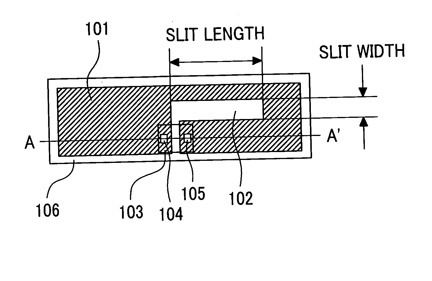
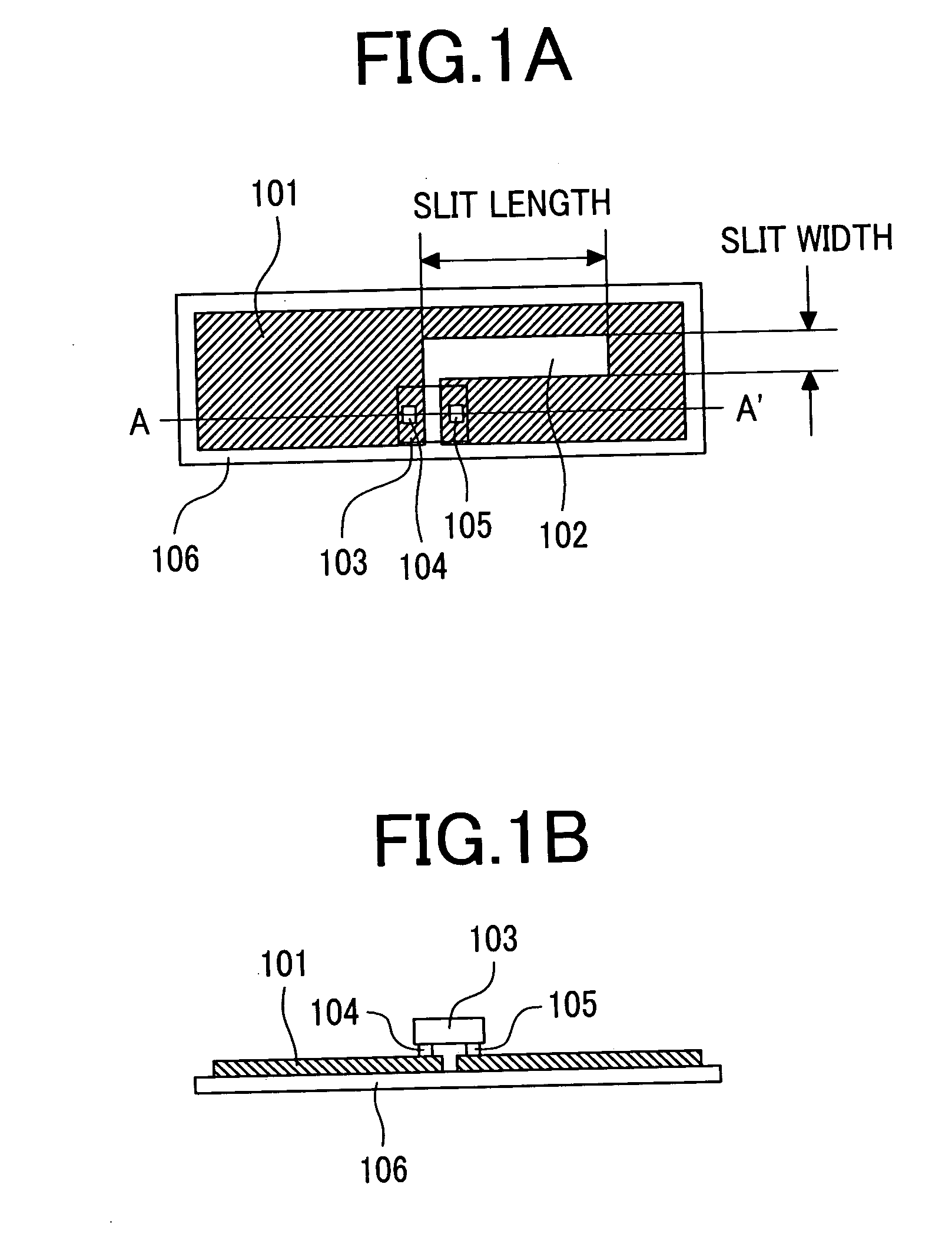
[0038]FIG. 1A is a plane view of RFID using an antenna according to this invention and FIG. 1B is a cross-sectional view taken along the line A-A′ of FIG. 1A.
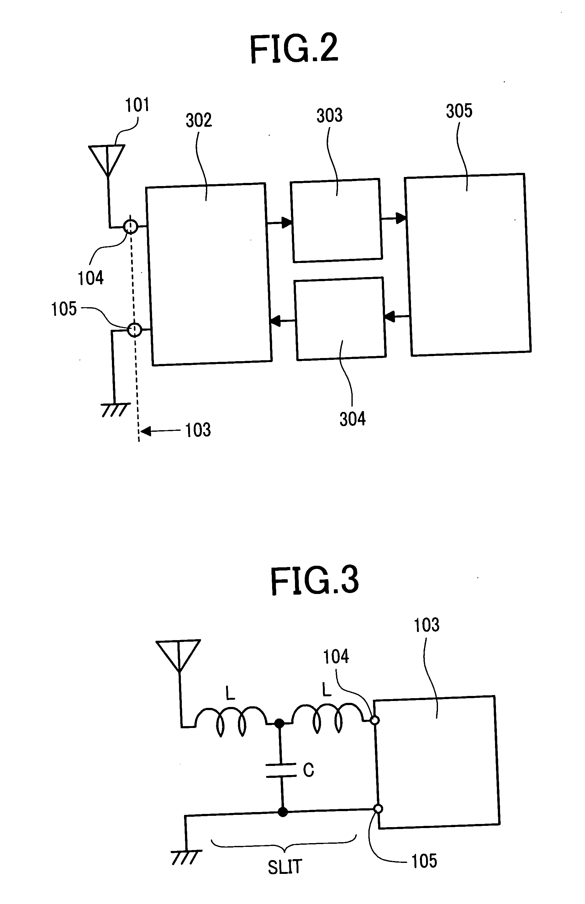
[0039] An antenna 101 is formed on a base film 106 using a conductive pattern and a slit 102 is established in the antenna 101. An RFID chip 103 is provided with a first bump 104 and a second bump 105 and the RFID chip 103 and the antenna 101 are connected to each other through the bumps 104 and 105 serving as connection points. The impedance between the bumps 104 and 105 (input impedance of the RFID chip 103) is adjusted to 60 ohms at 2.45 gigahertz, for instance. It should be noted that a construction may also be used in which the length of the antenna is shortened by using a high-dielectric-constant base material as the base film 106.
[0040] In the embodiment of this invention, by providing the antenna 101 with the slit 102, impedance matching between the antenna 101 and the RFID chip 103 is established.
[0041] When a microw...
second embodiment
[0065]FIG. 6A is a plane view of RFID using an antenna according to this invention and FIG. 6B is a cross-sectional view taken along the line A-A′ of FIG. 6A.
[0066] The antenna according to the second embodiment is a shortened antenna where the edge of the antenna is set close to the slit by narrowing the outer width of the antenna 501 (by setting the width of the conductor forming the antenna to 1 millimeter or less, for instance). It should be noted that each construction element that functions in the same manner as in the first embodiment described above is given the same reference numeral and the detailed description thereof will be omitted.
[0067] In the second embodiment, an antenna 501 is formed by a conductive pattern on a base film 106 and a slit 102 is established in the antenna 501. Also, the antenna 501 is connected to a first bump 104 and a second bump 105 provided for an RFID chip 103.
[0068]FIG. 7A is a plane view of RFID using an antenna as a modification according t...
third embodiment
[0071]FIG. 8A is a plane view of RFID using an antenna according to this invention and FIG. 8B is a cross-sectional view taken along the line A-A′ of FIG. 8A.
[0072] The antenna according to the third embodiment is characterized in that a high-dielectric-constant cover sheet 702 is provided for the upper surface of the antenna 601. It should be noted that each construction element that functions in the same manner as in the first or second embodiment described above is given the same reference numeral and the detailed description thereof will be omitted.
[0073] In the third embodiment, an antenna 601 is formed by a conductive pattern on a high-dielectric-constant base film 701 and a slit 602 is established in the antenna 601. Also, the antenna 601 is connected to a first bump 104 and a second bump 105 provided for an RFID chip 103.
[0074] As described above, in the third embodiment, the high-dielectric-constant cover sheet 702 is provided so as to cover the upper surface of the anten...
PUM
 Abstract
Description
Claims
Application Information