Display Apparatus

Inactive Publication Date: 2005-06-23
CITIZEN WATCH CO LTD
View PDF1 Cites 41 Cited by
  • Summary
  • Abstract
  • Description
  • Claims
  • Application Information

AI Technical Summary

Benefits of technology

[0020] The present invention has the effect of being able to set the number of pixels for a high-resolution display area independently of the number of signal lines in a display apparatus that has a plurality of signal lines (signal electrodes) and a plurality of scanning lines (scanning electrodes) and that produces a plurality of display areas of different resolutions on a single display panel by time division driving.
[0021] Furthermore, since there is no need to make the signal (pixel) electrodes in the main display section correspond on

Problems solved by technology

However, with the technique disclosed in Patent Document 1, as the character screen and the bar code screen are displayed at the same resolution, the resolution of the display panel has had to be made to match the resolution required of the bar code display; that is, even when a low resolution suffices for the display of the character screen, the entire display panel has had to be designed to provide the high resolution required of the bar code display, resulting in the problem that the display panel requires the use of higher performance driving circuits, etc.

Method used


Image

  • Display Apparatus
  • Display Apparatus
  • Display Apparatus

Examples


embodiment 1

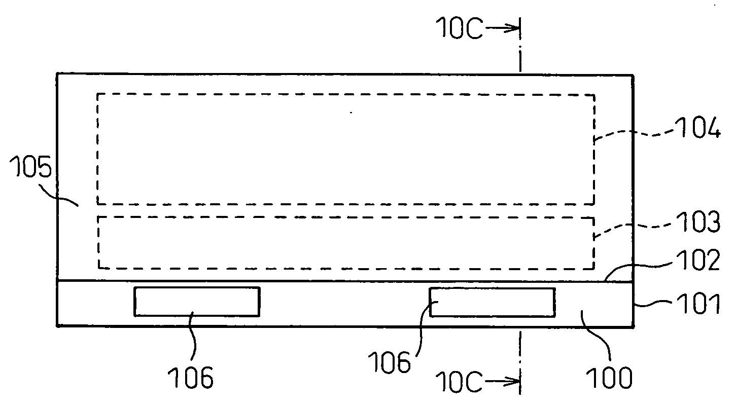
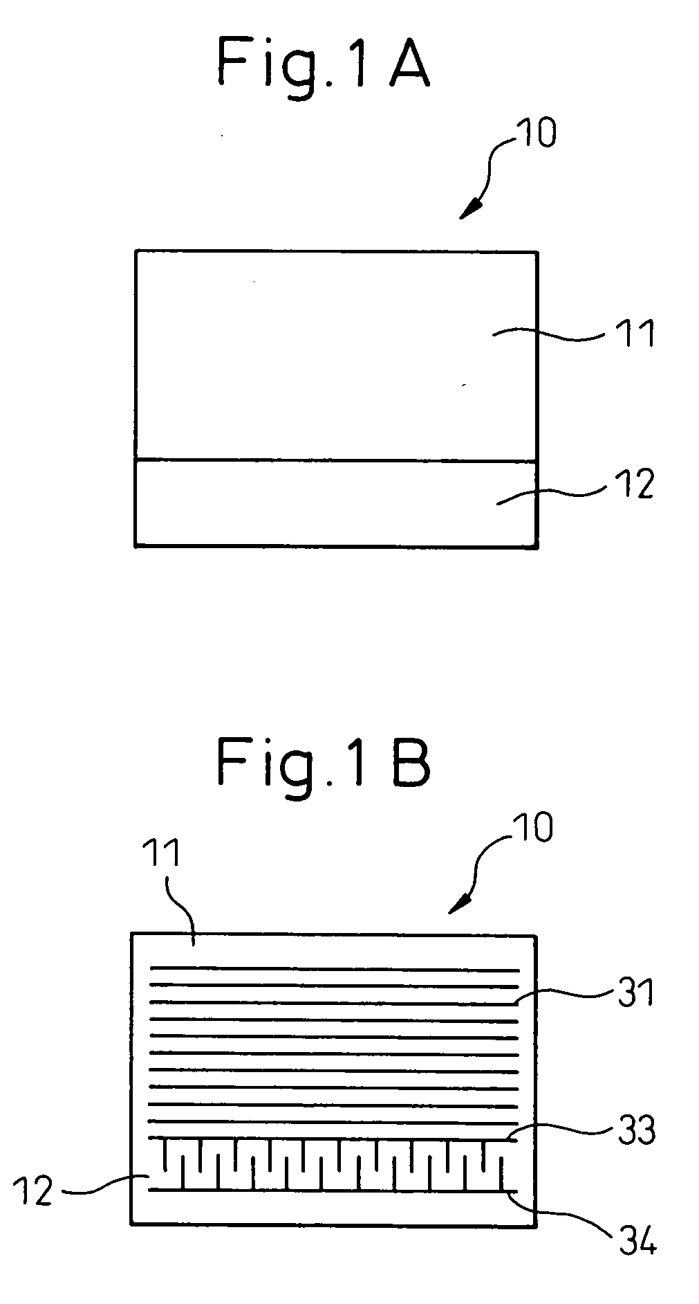
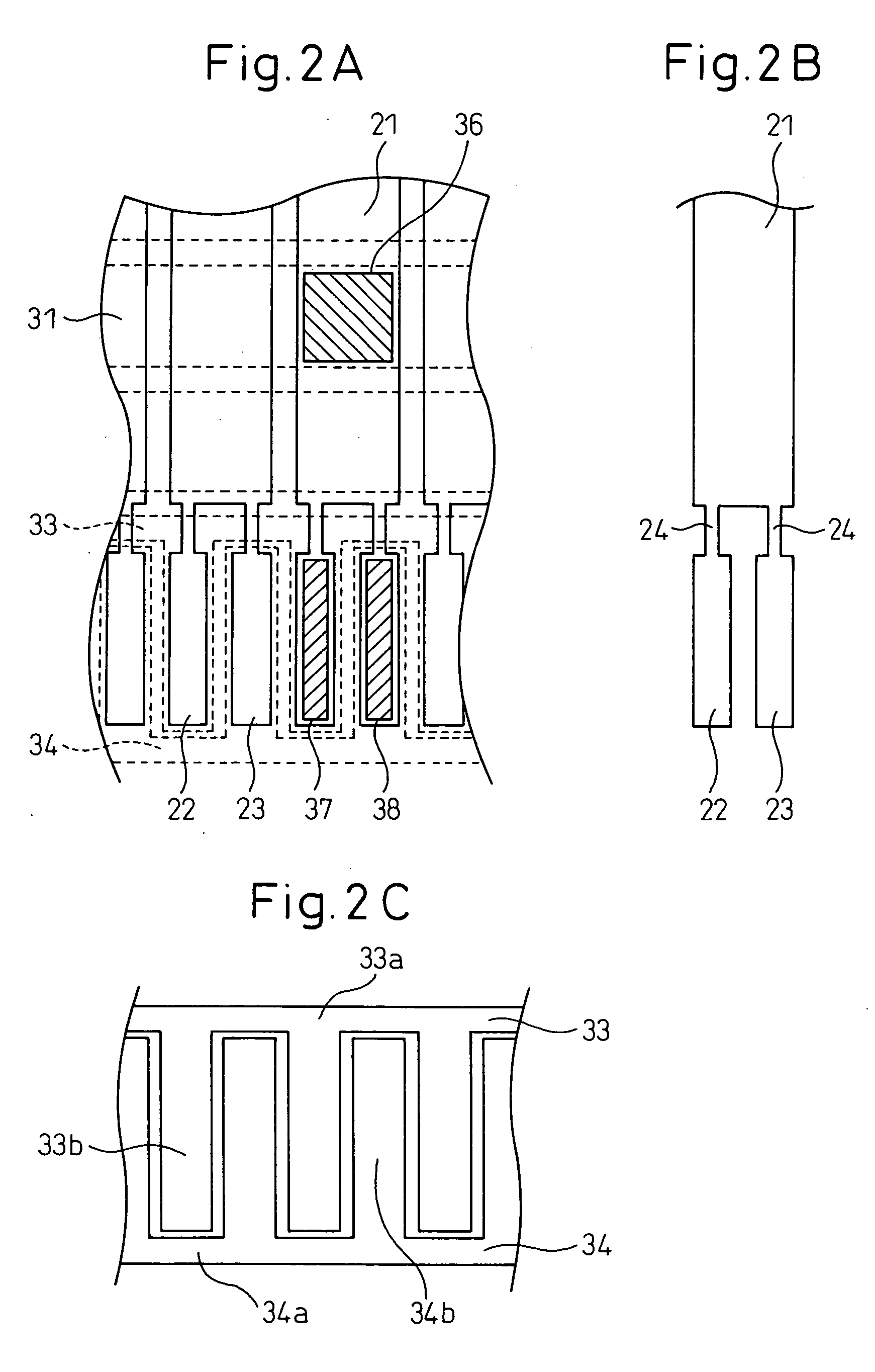
[0049]FIGS. 1, 2, and 3 are diagrams showing the first embodiment of the present invention. FIG. 1 shows a liquid crystal panel according to the first embodiment: FIG. 1A is a plan view of the liquid crystal panel, and FIG. 1B is a plan view schematically showing an array of scanning electrodes. FIG. 2 presents enlarged plan views showing essential portions of electrodes: FIG. 2A shows the spatial relationship between signal electrodes and scanning electrodes (their positional relationship as viewed from the top), FIG. 2B shows the plan shape of a signal electrode taken from FIG. 2A, and FIG. 2C shows the plan shape of a portion of the scanning electrodes in a sub display section. In FIG. 2, the sub display section is shown by reducing its size, top to bottom, for illustrative purposes. FIG. 3 is a plan view showing the liquid crystal panel of the first embodiment.

[0050] An outline of the liquid crystal panel 10 will be described with reference to FIG. 3. A main display section 11 ...

embodiment 2

[0061] The second embodiment will be described with reference to FIG. 4. In the second embodiment, the sub display section 42 is located in one corner of the liquid crystal panel 40. FIG. 4A is a plan view of the liquid crystal panel, and FIG. 4B is a plan view schematically showing an array of scanning electrodes.

[0062] The arrangement of the main display section 41 and the sub display section 42 will be described with reference to FIG. 4A. The sub display section 42 is disposed in the lower right corner of the liquid crystal panel 40, and the area other than the sub display section 42 is allocated as the main display section 41. The liquid crystal panel 40 is a passive liquid crystal panel, as in the first embodiment.

[0063] The electrode configuration and the driving method will be described with reference to FIG. 4B. The scanning electrodes 41 are divided into two groups, one consisting of main scanning electrodes 43 and 44 formed in the main display section 41 and the other co...

embodiment 3

[0069] The third embodiment will be described with reference to FIG. 5. FIG. 5A shows how the signal electrodes overlap the scanning electrodes in a two-dimensional plane, and FIG. 5B shows the sub scanning electrodes in the sub display section. In FIG. 5A, the signal electrode configuration differs from the first and second embodiments in that each signal electrode comprises one main signal electrode 51 and three sub-signal electrode portions 53, 54, and 55 connected to it by thin wiring lines (narrow path portions: line width is about 10 μm); otherwise, the configuration is the same. Here, the sub-signal electrode portion 53 indicates the leftmost one of the three horizontally arranged sub-signal electrodes of the signal electrode 50. Likewise, 54 indicates the middle one, and 55 indicates the signal electrode portion located at the rightmost end.

[0070] In FIG. 5B, the upper sub scanning electrode 56 is formed in the shape of a comb whose teeth are pointed downward, and the pitch...


PUM


Abstract

In displaying a price label, the price can be displayed at low resolution without any problem, but a bar code requires a high resolution display. In view of this, the invention provides an electrode structure for a display apparatus that can suppress increases in cost and power consumption while preventing image quality degradation, even when a low-resolution display area and a high-resolution display area are mixed on the same display. A liquid crystal panel 10 has a main display section 11 and a sub-display section 12. In the main display section 11, pixels are arranged in a matrix pattern. In the sub display section 12, rectangle-shaped pixels are arranged in a single row, and the pixel pitch in the sub display section 12 is m/n of that in the main display section 11 (n and m are integers).

Description

CROSS-REFERENCE TO RELATED APPLICATION [0001] This application claims priority from, and incorporates by reference the entire disclosure of, the following Japanese Patent Applications, [0002] (1) No. 2003-325378, filed on Sep. 18, 2003. [0003] No. 2004-069888, filed on Mar. 12, 2004. BACKGROUND OF THE INVENTION [0004] 1. Field of the Invention [0005] The present invention relates to a display apparatus that produces a display by applying a voltage to an electro-optical conversion material and, more particularly, to a display apparatus having display areas of different resolutions, wherein the electro-optical conversion material is a liquid crystal material. [0006] 2. Description of the Related Art [0007] In the fields of various measuring instruments, electronic shelf labeling systems, etc., it is practiced to produce a display of ordinary characters, graphics, or the like, which does not require a particularly high resolution, and a display of bar code or the like, which requires a...

Claims


Application Information

Patent Timeline
IPC IPC(8): G02F1/1343G02F1/1368G09F9/30G09F9/35G09G3/36
CPCG02F1/134309G09G2380/04G09G2300/0439G09G3/3648
Inventor KAMIYA, KIYOSHITAJIMA, EIICHIOCHI, ISAO
Owner CITIZEN WATCH CO LTD
Why Eureka
Try Eureka