Method and apparatus for video deinterlacing and format conversion

a video and format conversion technology, applied in the field of digital video formatting, can solve the problems of low-cost line-based process, known to produce “jaggies”, and particularly lack of vertical detail

Active Publication Date: 2005-06-23
AVAGO TECH INT SALES PTE LTD
View PDF26 Cites 87 Cited by
  • Summary
  • Abstract
  • Description
  • Claims
  • Application Information

AI Technical Summary

Benefits of technology

[0010] The objects, features and advantages of the present invention include providing a method and an apparatus for video deinterlacing and format conversion that may (i) eliminate an exhaustive evaluation of all candidate directions by exploiting a convex nature of a metric search space, (ii) reuse identical silicon for both intra-mode estimation and edge detection for deinterlacing, (iii) use a different number of filter taps for vertical interpolation compared to directional interpolation, (iv) exploit homogeneity along edges that may be strong and regular enough to be detected without admitting artifacts from false detects, (v) prevent artifacts in areas containing small apertures, (vi) detect static horizontal edges, (vii) detect static areas of small spatial extent, (viii) reduce a severity of artifacts from false angle detections, (ix) increase a confidence level of decisions, (x) provide a robust and correct confidence estimation for an angle detection, (xi) refine a decision between angles adjacent to a best angle detected by a first rough and cheap estimator, (xii) operate at a lower clock speed, (xiii) reduce microprocessor utilization, (xiv) reduce silicon area by re-using silicon designed for video compression for an additional task of deinterlacing, (xv) reduce interpolation complexity for non-vertical directional interpolation without sacrificing quality, (xvi) permit a detection of edges to be more aggressive in areas without small apertures thereby increasing visual performance on edges without increasing artifacts from false detections, (xvii) reduce annoying flickering artifacts, (xviii) increase quality of low-contrast and marginally detectable edges, (xix) increase correction detection probability, (xx) reduce false detection probability and / or (xxi) increase quality through decreasing a probability of detecting an angle adjacent to an optimal angle.

Problems solved by technology

A resulting lack of vertical detail is particularly noticeable for sharp edges.
Weave (i.e., temporal filter) is known to produce “jaggies” (i.e., interlace artifacts that are extremely objectionable for moving objects).
The VT-filtering is a fixed (i.e., non-adaptive) low-cost line-based process that is cost effective to implement in silicon but is known to produce temporal artifacts (i.e., trailing edges or “edge ghosts” from previous fields appear behind moving objects).
Weave is a good option for still portions of video and a poor choice for moving areas.
Hard block-level decisions in motion adaptive techniques can lead to objectionable blocking artifacts.
However, more advanced motion adaptive deinterlacing techniques that combine weave and bob suffer mainly from relatively poor performance for moving video due to all the drawbacks of bob.
A disadvantage of the motion compensated technique is that motion estimation is often more expensive than any of the previously mentioned techniques.
If motion estimation fails on the video sequence (i.e., highly irregular motion, non-smooth motion fields or various lighting effects), motion compensated techniques may be no better than less complex methods.
In practice, however, motion compensated deinterlacing increases vertical detail while reducing flickering artifacts on a broad range of video, such that a common drawback is simply complexity.
To a lesser extent than bob, edge-based spatial filtering also suffers from lack of vertical detail.
In particular, high frequency textures that lack edges will not be improved over simple bob.

Method used


Image

  • Method and apparatus for video deinterlacing and format conversion
  • Method and apparatus for video deinterlacing and format conversion
  • Method and apparatus for video deinterlacing and format conversion

Examples


Embodiment Construction

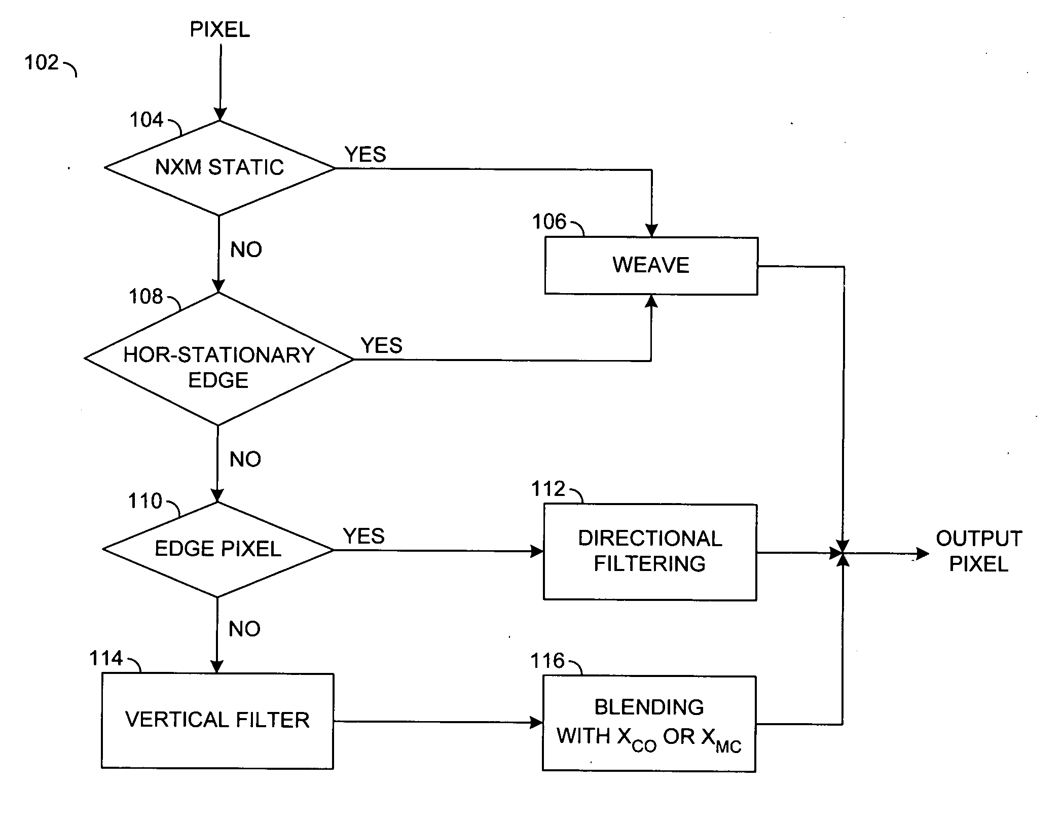
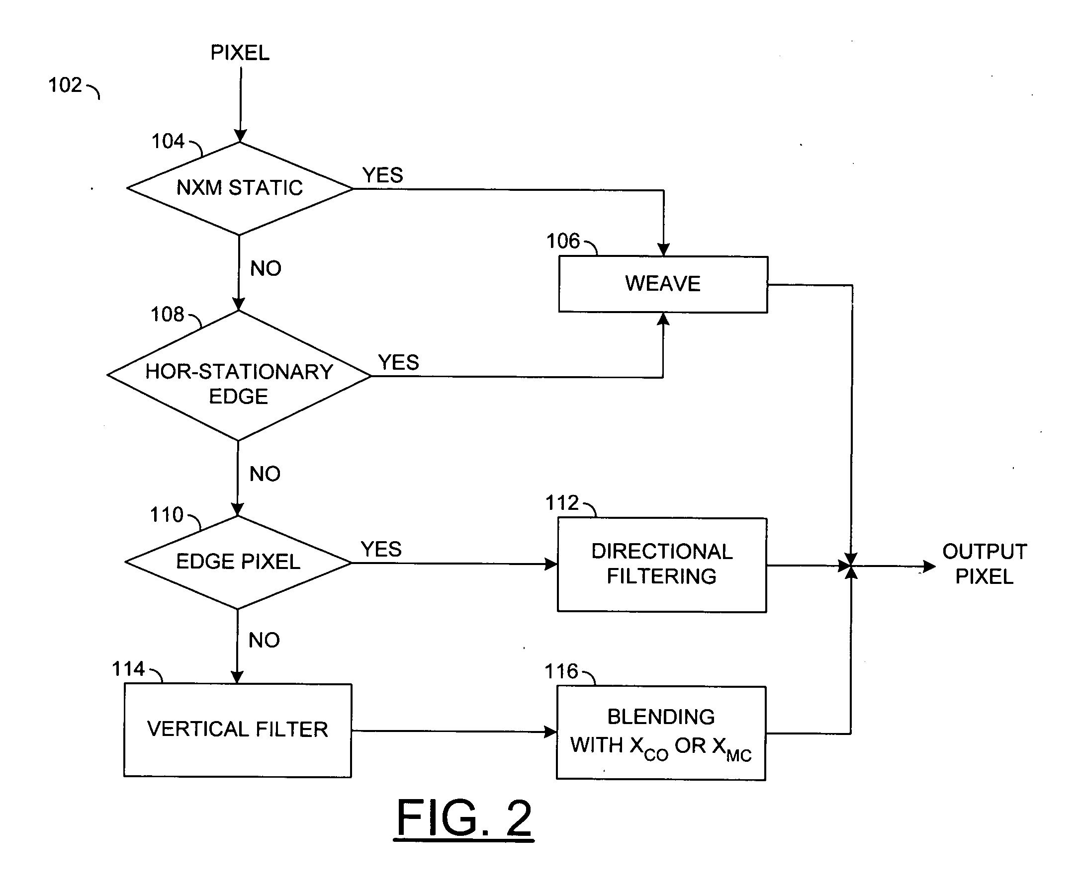
[0031] The present invention may be realized as a low-cost high quality deinterlacing technique. The technique may provide spatial filtering by considering directional information at a pixel level in a field. Low cost may be realized through the following methods that may be optionally applied to reduce implementation complexity. The implementation complexity may depend on an application platform (e.g., fully custom hardware, hardware processor extension or full software implementation).

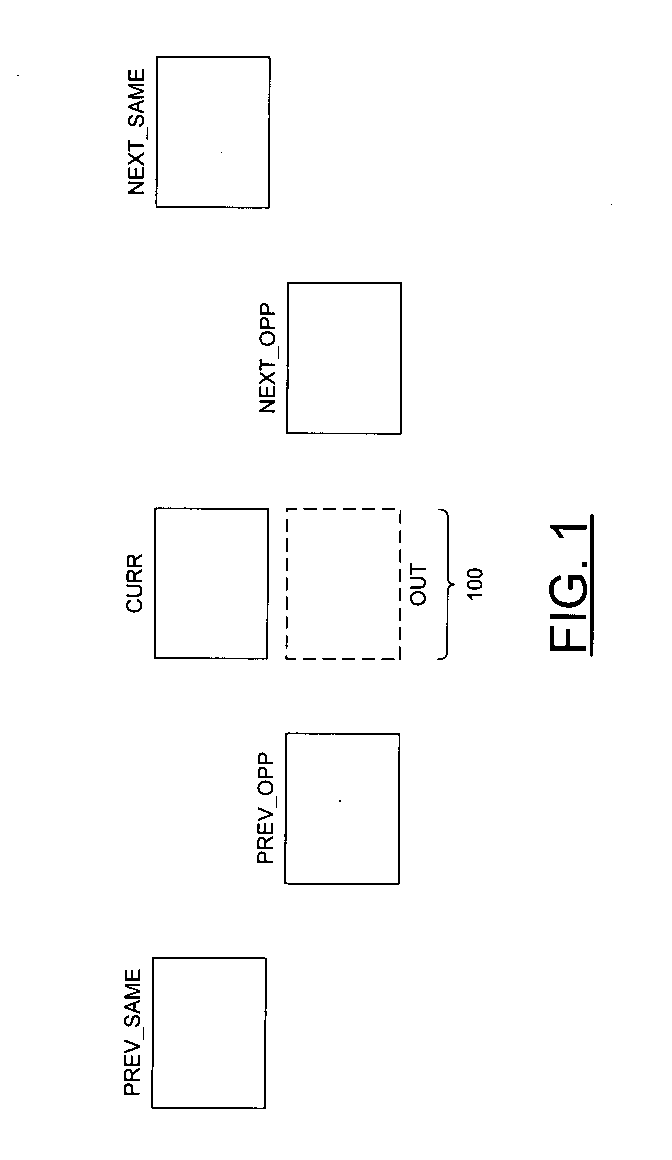
[0032] Referring to FIG. 1, a block diagram of an example field availability is shown. A frame 100 in a picture may be generated by calculating an interpolated field (e.g., OUT) interlaced with a current field (e.g., CURR) of the picture. Generation of the interpolated field OUT may be performed using one or more of (i) a first previous field (e.g., PREV_OPP) having an opposite parity (e.g., top or bottom, odd or even) as the current field CURR, (ii) a second previous field (e.g., PREV_SAME) having ...


PUM


Abstract

A method for deinterlacing a picture is disclosed. The method generally includes the steps of (A) determining a protection condition by performing a static check on the picture in a region around a location interlaced with a first field of the picture, (B) calculating an interpolated sample at the location by temporal averaging the first field with a second field in response to the protection condition indicating significant vertical activity and (C) calculating the interpolated sample at the location by spatial filtering the first field in response to the protection condition indicating insignificant vertical activity.

Description

[0001] The present invention is related to co-pending U.S. patent application Ser. No. 10 / 727,476, filed Dec. 4, 2003 and Ser. No. ______ (Attorney Docket number 03-1922 / 1496.00349), filed concurrently, which are hereby incorporated by reference in their entirety.FIELD OF THE INVENTION [0002] The present invention relates to digital video formatting generally and, more particularly, to a method and an apparatus for video deinterlacing and format conversion. BACKGROUND OF THE INVENTION [0003] Digital images and video come in a large variety of formats. For many applications, converting between two or more different formats is desirable. A high-quality low-cost method for converting the digital signals is very useful for such applications as: (1) converting interlaced NTSC video at 60 fields / second to progressive video with a similar or larger horizontal and vertical resolution at 60 frames / second for display on progressive televisions, (2) performing a high-quality “zoom” function on...

Claims


Application Information

Patent Timeline
Patent Type & Authority Applications(United States)
IPC IPC(8): H04N5/44H04N11/20
CPCH04N7/012
Inventor WINGER, LOWELL L.JIA, YUNWEIWELLS, AARON G.LINZER, ELLIOT N.BOOTH, SIMONCOTE, GUY
Owner AVAGO TECH INT SALES PTE LTD
Why Eureka
Try Eureka