Positioning device

a positioning device and positioning technology, applied in the direction of mounting arm assemblies, magnetic recording, maintaining head carrier alignment, etc., can solve the problems of high precision and cost of air bearings of this kind, comparatively expensive design, and disadvantages in precision and etc., to achieve accurate positioning, short seek and settle time, and low manufacturing cost

Inactive Publication Date: 2005-06-23
DR JOHANNES HEIDENHAIN GMBH
View PDF5 Cites 9 Cited by
  • Summary
  • Abstract
  • Description
  • Claims
  • Application Information

AI Technical Summary

Benefits of technology

[0007] According to an example embodiment of the present invention, a positioning device may be provided, which may allow for exceedingly precise positioning as well as very short seek and settle times at comparatively low manufacturing cost and simple operation.

Problems solved by technology

In this instance, there is considerable expenditure involved in positioning the scanning unit relative to the swivel arm.
Air bearings of this kind may require a highly precise and costly manufacture and a permanent compressed air supply.
Conventional positioning devices may have the disadvantage that they either have a comparatively costly design and / or may be disadvantageous in terms of precision and seek and settle time.
In conventional bearings, this elasticity causes a comparatively vibration-sensitive or oscillation-prone behavior of the positioning device as a whole.

Method used


Image

  • Positioning device
  • Positioning device
  • Positioning device

Examples


Embodiment Construction

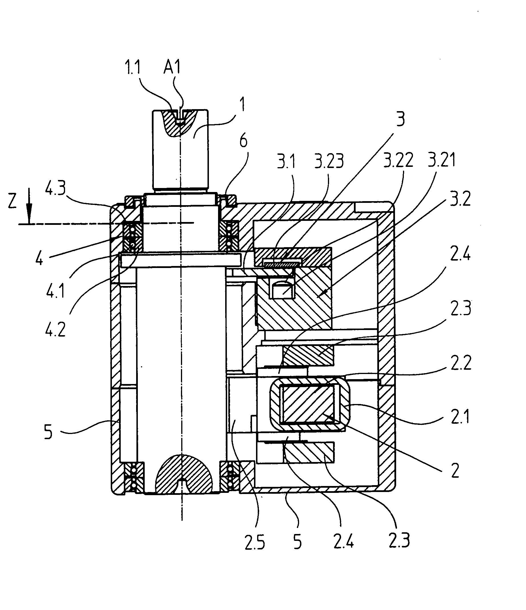
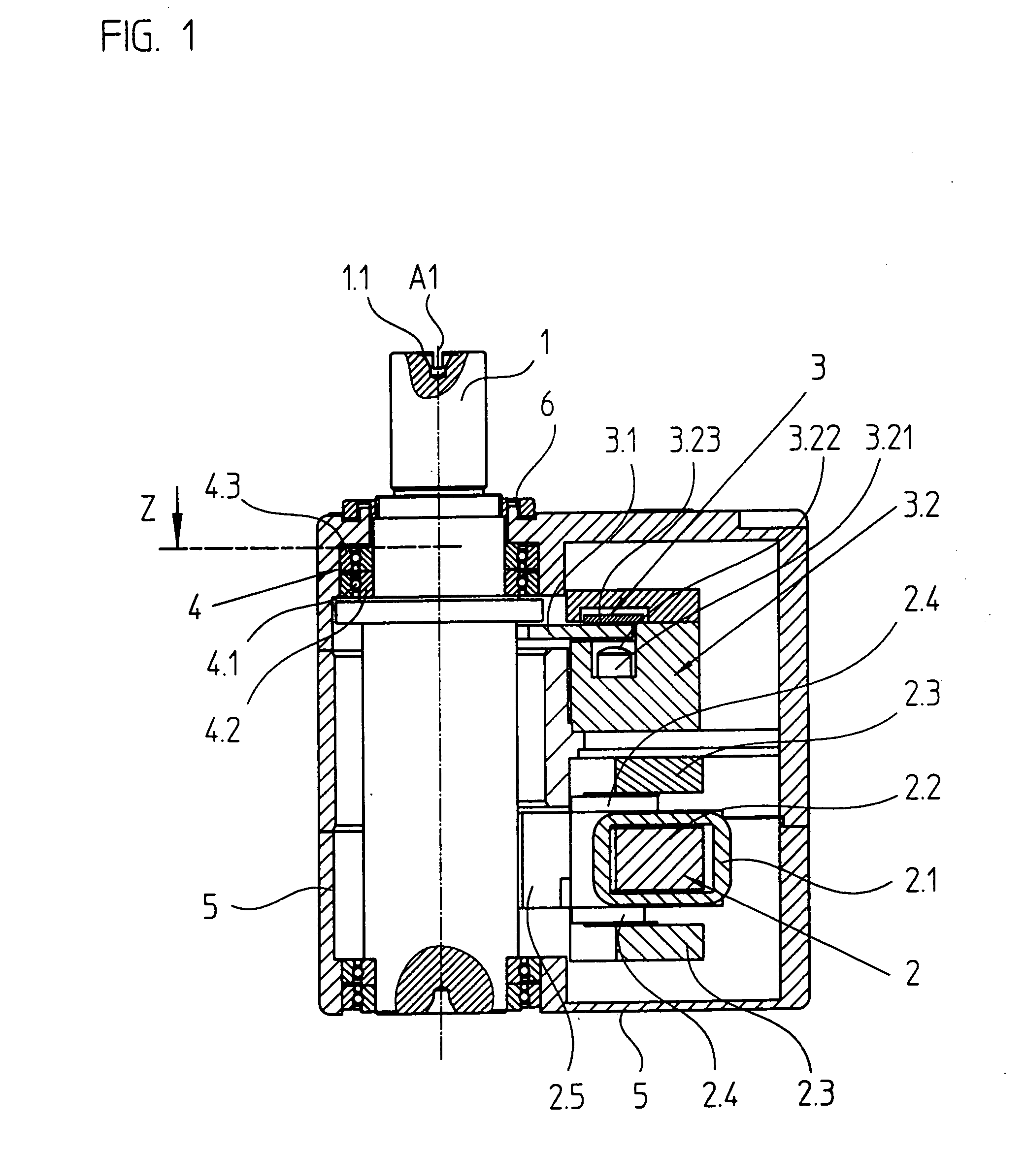
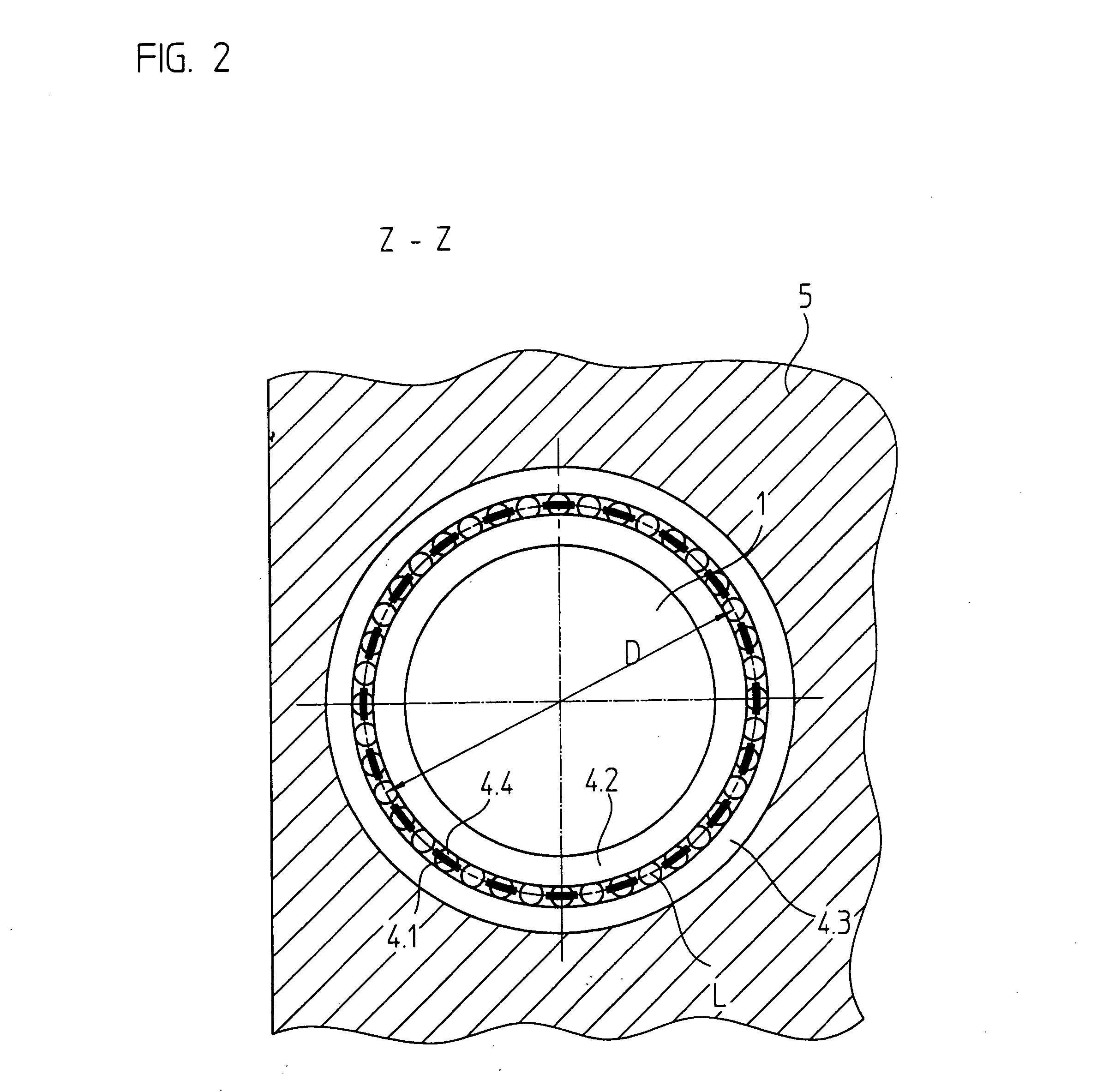
[0028]FIG. 1 illustrates a positioning device as it is used in connection with STWs. According to this drawing, a shaft 1 is able to swivel about an axis A1 and has a shaft end 1.1, to which a swivel arm for writing on a hard disk may be attached. At the passage of shaft 1 through a housing 5 a seal is installed. The shaft 1 in the exemplary embodiment shown is made of steel.

[0029] The swivel motion, the exemplary embodiment illustrated allowing for a swivel range of ±25°, is initiated by a so-called voice coil motor 2, an electrical direct drive. The primary part 2.1 of voice coil motor 2, which in the example illustrated works as a rotor within the swivel range, includes a copper coil 2.1 surrounding a ferromagnetic core 2.2. Corresponding to the swivel range, the ferromagnetic core 2.2 extends along the line of a partial circle. The windings of the copper coil 2.1 are arranged such that they are parallel to the drawing plane in FIG. 1. In the operation of voice coil motor 2, fer...


PUM

PropertyMeasurementUnit
lengthaaaaaaaaaa
lengthaaaaaaaaaa
circumferential lengthaaaaaaaaaa

Abstract

A positioning device includes a swiveling shaft, at one end of which an element to be positioned may be attached, a swivel drive, made up of a rotor, which is movable relative to a stator, a position measuring device, made up of two parts movable relative to each other, and a roller bearing, which includes several rolling elements. The rotor of the swivel drive and a first part of the position measuring device are connected to the shaft in a rotatably fixed manner. The rolling elements are made of a ceramic material.

Description

CROSS-REFERENCE TO RELATED APPLICATIONS [0001] The present application claims priority to Application No. 103 57 295.3, filed in the Federal Republic of Germany on Dec. 5, 2003, which is expressly incorporated herein in its entirety by reference thereto. FIELD OF THE INVENTION [0002] The present invention relates to a positioning device, which may be suitable, for example, for the precise movement of a swivel arm for a servo track writer. BACKGROUND INFORMATION [0003] Positioning devices of this type are often used in servo track writers (STW), in which the tracks for magnetizable hard disks are formatted or written. For this purpose, a positioning device in the STW swivels a shaft, to which a swivel arm is attached. At its end, a write head is provided, which is ultimately moved by the swivel motion of the shaft and is positioned in a highly precise manner so that as many tracks as possible per unit surface area of the hard disk may be configured. The number of tracks set up per un...

Claims


Application Information

Patent Timeline
Patent Type & Authority Applications(United States)
IPC IPC(8): G11B5/48G11B5/55G11B5/596G11B21/02
CPCG11B5/4813
Inventor HOEFER, VOLKERLAHR, JOHANNMITTERREITER, JOHANNSCHEGLMANN, GERHARD
Owner DR JOHANNES HEIDENHAIN GMBH
Why Eureka
Try Eureka