
Two-way QKD system with active compensation

a two-way qkd and active compensation technology, applied in the field of quantum cryptography, can solve the problems of time variance of quantum signal polarization, difficult modulation of signal and keeping interferometer balanced, and add complexity and expense to the system

Inactive Publication Date: 2005-06-23
MAGIQ TECH INC
View PDF10 Cites 33 Cited by
  • Summary
  • Abstract
  • Description
  • Claims
  • Application Information

AI Technical Summary

Benefits of technology

[0014] A third aspect of the invention is a method of performing QKD The method includes forming two quantum signals and two control signals in a first interferometer loop of a first QKD station having first and second interferometer loops. The control signals precede the quantum signals. The method also includes transmitting the control signals and quantum signals to a second QKD station that modulates at least one of the quantum signals and returns the quantum signals and the control signa

Problems solved by technology

As a consequence, an eavesdropper (“Eve”) that attempts to intercept or otherwise measure the quantum signal will introduce errors into the transmitted signals, thereby revealing her presence.
There are two main problems with such one-way interferometers used for QKD.
One problem involves time variance of the quantum signal polarization.
One needs to know the polarization state of the quantum signal precisely as it arrives at Bob's apparatus, otherwise it is very difficult to modulate the signal and keep the interferometer balanced.
However, this adds complexity and expense to the system, as well as unwanted attenuation.
Also, a polarization scrambler placed at Alice decreases the system's security and adds additional complexity and expense to the system, as well as unwanted attenuation.
Another problem with a one-way QKD system involves temperature drift in the interferometer, which causes a phase shift that destroys the intended interference.
In a real-world version of the system of the '935 patent, the sending and receiving stations are separated by a great distance so that they have to be independently thermally controlled, which adds complexity and expense to a commercially viable version of the '935 patent QKD system.
Thus, as the bit rate goes up, the probability of finding both an outgoing and an incoming pulse passing through the modulator at the same time increases, thereby limiting the system's bit rate.

Method used


Image

  • Two-way QKD system with active compensation
  • Two-way QKD system with active compensation
  • Two-way QKD system with active compensation

Examples


Embodiment Construction

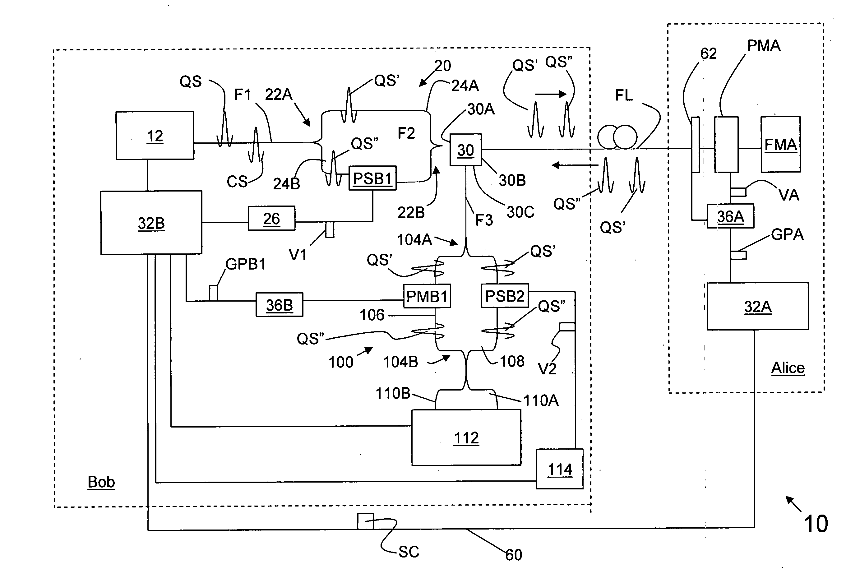
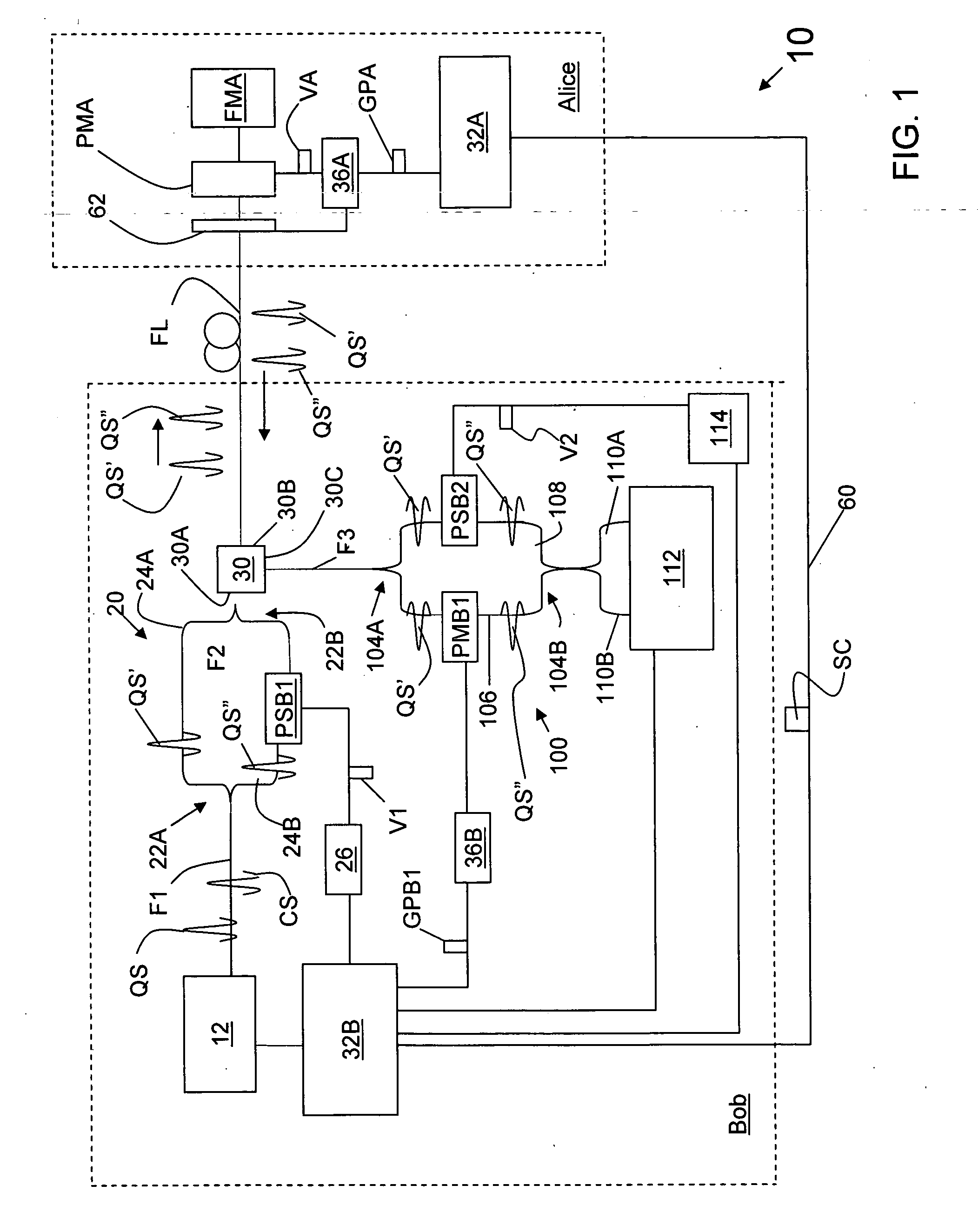
[0027] The present invention relates to quantum cryptography, and in particular relates to a stabilized two-way quantum key exchange (QKD) system. The present invention includes a two-way QKD system that is actively stabilized. The design of the system allows for a higher bit rate than that possible with prior art two-way systems that rely on autocompensation by having signals traverse identical paths. Several different embodiments of the invention are described below. A so-called “two-loop” embodiment is first described, and then the other embodiments are described in relation to the two-loop embodiment.

[0028] In the description below, “loop” is sometimes used as shorthand for “interferometer.” Also, the phrase “quantum signals” is used to denote those signals (optical pulses) associated with a quantum channel and that are used to establish a quantum key. Initially, the quantum signals leaving Bob need not be “quantum signals” in the literal sense, i.e., they need not have a photo...


PUM


Abstract

A two-way actively stabilized QKD system that utilizes control signals and quantum signals is disclosed. Because the quantum signals do not traverse the same optical path through the system, signal collisions in the phase modulator are avoided. This allows the system to have a higher transmission rate than a two-way system in which the quantum signals traverse the same optical path. Also, the active stabilization process, which is based on maintaining a fixed relationship between an intensity ratio of interfered control signals, is greatly simplified by having the interferometer loops located all in one QKD station.

Description

CLAIM OF PRIORITY [0001] This patent application claims priority from U.S. Provisional Patent Application Serial No. 60 / 531,724, entitled “Stabilized one-way QKD system,”filed on Dec. 22, 2003, which patent Application is incorporated by reference herein.FIELD OF THE INVENTION [0002] The present invention relates to quantum cryptography, and in particular relates to quantum key distribution (QKD) systems. BACKGROUND OF THE INVENTION [0003] Quantum key distribution involves establishing a key between a sender (“Alice”) and a receiver (“Bob”) by using weak (e.g., 0.1 photon on average) optical signals transmitted over a “quantum channel.” The security of the key distribution is based on the quantum mechanical principal that any measurement of a quantum system in unknown state will modify its state. As a consequence, an eavesdropper (“Eve”) that attempts to intercept or otherwise measure the quantum signal will introduce errors into the transmitted signals, thereby revealing her presen...

Claims


Application Information

Patent Timeline
IPC IPC(8): G02F1/335H04B10/516H04B10/548H04B10/61H04B10/70H04K1/00H04L9/08
CPCH04L9/0852
Inventor ZAVRIYEV, ANTONTRIFONOV, ALEXEILAGASSE, MICHAEL
Owner MAGIQ TECH INC
Learn More