Apparatus and method for performing electrically band-limited optical differential phase shift keying modulation

a technology of optical differential and analog signal, applied in the field of optical modulation schemes, can solve the problems of inability to narrow the interval between channels, limit the nrz modulation scheme, and modulated optical signals may be sensitive to dispersion, so as to reduce crosstalk

Inactive Publication Date: 2005-06-23
ELECTRONICS & TELECOMM RES INST
View PDF9 Cites 19 Cited by
  • Summary
  • Abstract
  • Description
  • Claims
  • Application Information

AI Technical Summary

Benefits of technology

[0009] Accordingly, the present invention has been made keeping in mind the above problems occurring in the prior art, and an object of the present invention is to provide an apparatus and method for performing electrically band-limited optical DPSK modulation, which can reduce crosstalk between adjacent channels and the influence of dispersion at the time of wavelength division multiplexing optical transmission.

Problems solved by technology

However, with the increase of the data rate of the optical transmission system, the limitations of the NRZ modulation scheme have appeared.
However, if the entire bandwidth corresponding to the data rate is used as in the case of the conventional scheme, there are problems in that, in the case of high-speed transmission in Wavelength Division Multiplexing (WDM) optical transmission, the spectrum of a modulated optical signal is widened, so that the modulated optical signal may be sensitive to dispersion and it is not possible to narrow an interval between channels.
However, the conventional methods are problematic in that influences due to crosstalk between adjacent channels and dispersion, occurring when high-speed transmission is performed using the DPSK modulation, cannot be solved.

Method used


Image

  • Apparatus and method for performing electrically band-limited optical differential phase shift keying modulation
  • Apparatus and method for performing electrically band-limited optical differential phase shift keying modulation
  • Apparatus and method for performing electrically band-limited optical differential phase shift keying modulation

Examples


Embodiment Construction

[0023] Hereinafter, embodiments of the present invention will be described in detail with reference to the attached drawings. Reference now should be made to the drawings, in which the same reference numerals are used throughout the different drawings to designate the same or similar components. In the present specification, if it is determined that a detailed description of related art or construction unnecessarily makes the gist of the present invention unclear, the detailed description thereof will be omitted.

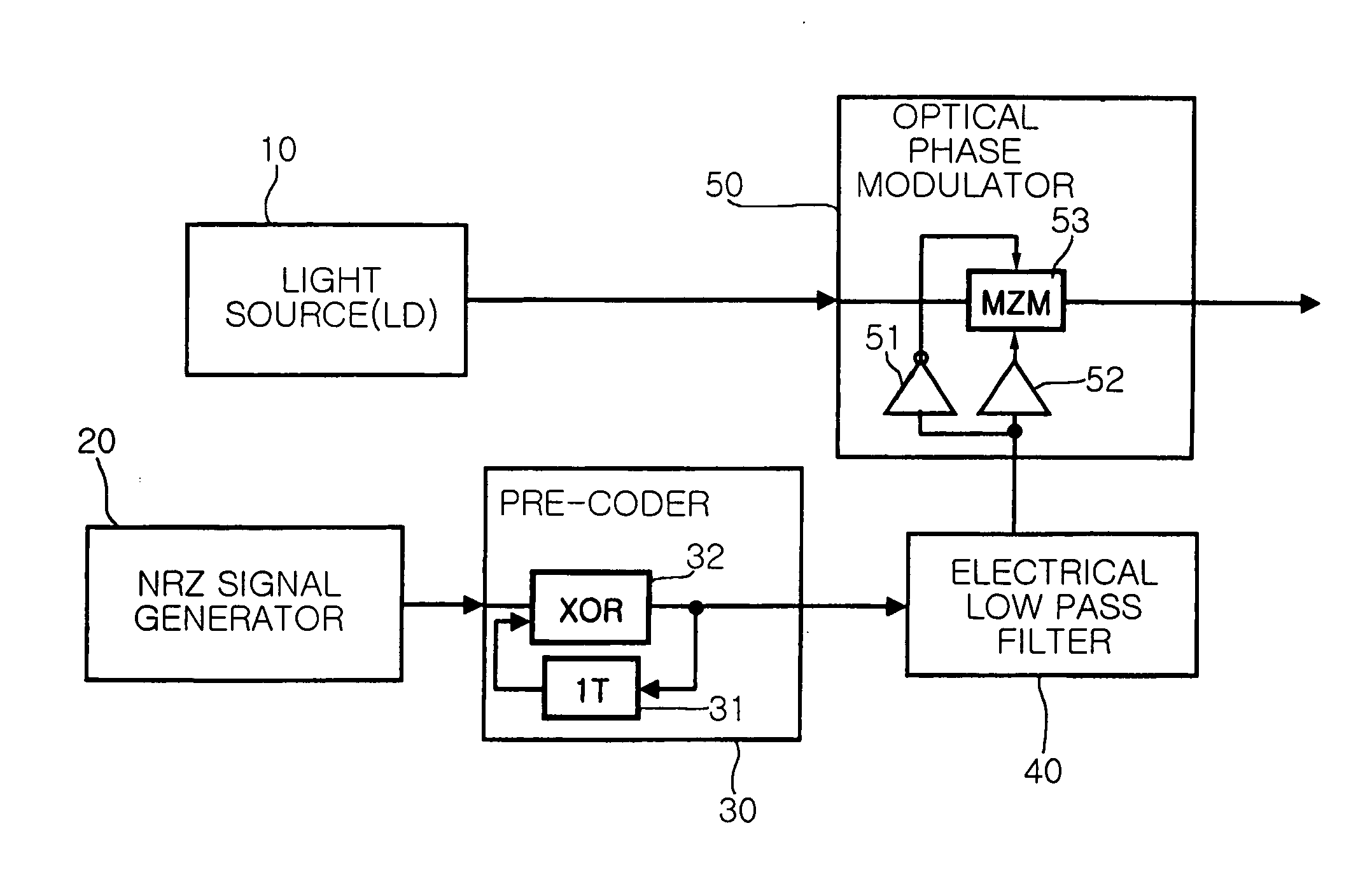
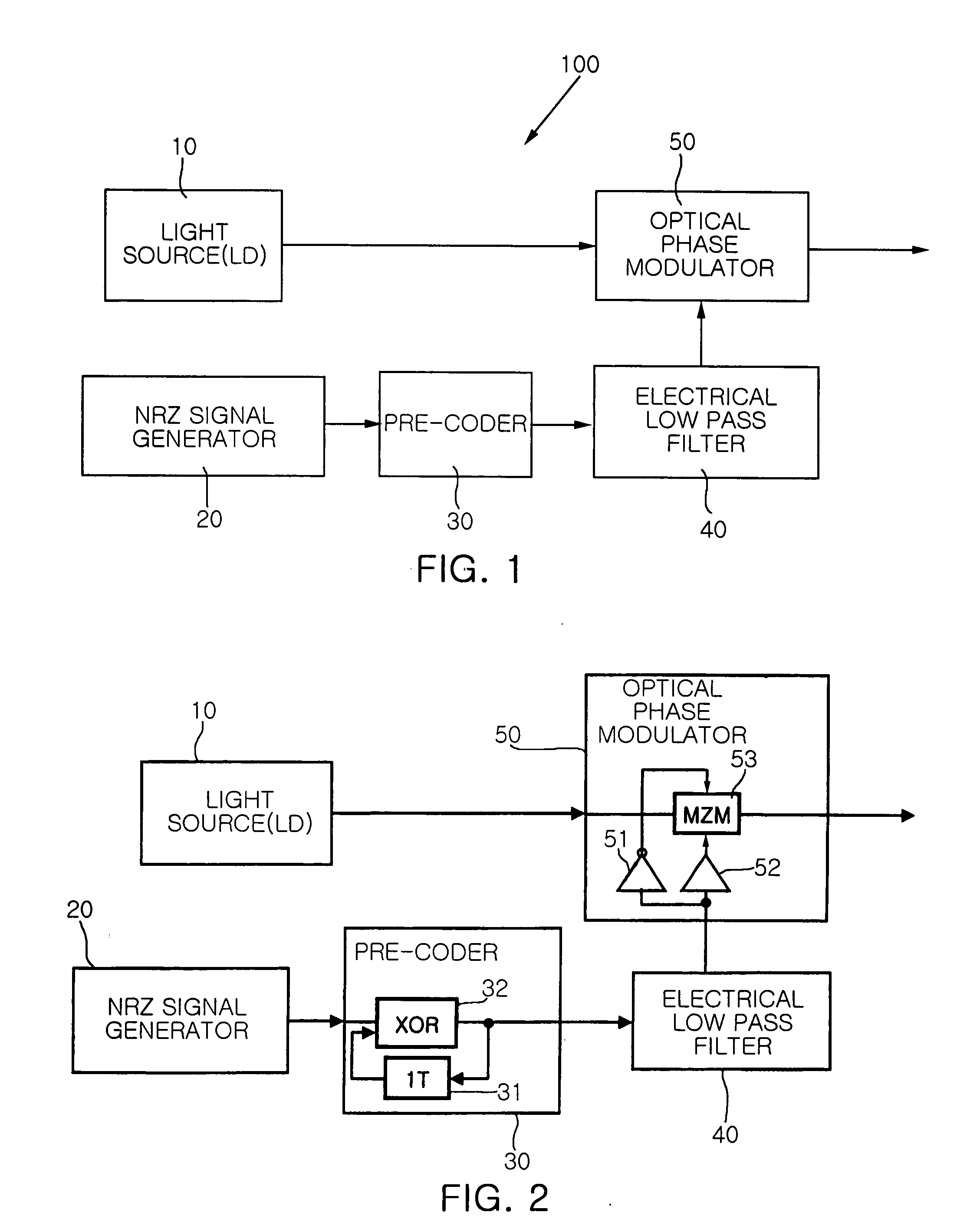
[0024]FIG. 1 is a view showing the construction of an optical DPSK modulating apparatus according to an embodiment of the present invention.

[0025] Referring to FIG. 1, an optical DPSK modulating apparatus 100 of the present invention includes a light source 10, a NRZ signal generator 20, a pre-coder 30, an electrical low pass filter 40 and an optical phase modulator 50. Hereinafter, the detailed functions of the optical DPSK modulating apparatus 100 and an electrically ban...


PUM

PropertyMeasurementUnit
lengthaaaaaaaaaa
electricallyaaaaaaaaaa
electrically bandaaaaaaaaaa

Abstract

The present invention relates to an apparatus and method for performing optical Differential Phase Shift Keying (DPSK) modulation, which transmits a phase difference between adjacent bits as information. The electrically band-limited optical DPSK modulating apparatus includes a light source, a Non-Return-to-Zero (NRZ) signal generator, a pre-coder, an electrical low pass filter, and a phase modulator. The NRZ signal generator generates a NRZ signal. The pre-coder codes the NRZ signal generated by the NRZ signal generator into a differential signal. The low pass filter electrically limits a bandwidth of the differential signal obtained through the pre-coder. The phase modulator modulates an optical signal input from the light source into a DPSK signal using the differential signal having the bandwidth electrically limited by the low pass filter.

Description

BACKGROUND OF THE INVENTION [0001] 1. Field of the Invention [0002] The present invention relates, in general, to optical modulation schemes and, more particularly, to an apparatus and method for performing optical differential phase shift keying modulation, which transmits a phase difference between adjacent bits as information. [0003] 2. Description of the Related Art [0004] In a current optical transmission system, a Non-Return-to-Zero (NRZ) modulation scheme has been generally used. However, with the increase of the data rate of the optical transmission system, the limitations of the NRZ modulation scheme have appeared. Therefore, a new modulation scheme has been developed. A Differential Phase Shift Keying (DPSK) modulation scheme is one of new modulation schemes. [0005] Generally, a DPSK modulation scheme, which transmits information using the phase of a transmitted carrier signal, includes information in a phase difference between adjacent bits and transmits the information. ...

Claims


Application Information

Patent Timeline
Patent Type & Authority Applications(United States)
IPC IPC(8): H04L27/18G02F1/01G02F1/21G02F1/225
CPCG02F1/0121G02F2201/126G02F2001/212G02F1/225G02F1/212H04L27/18
Inventor HAN, JIN SOOJANG, YOUN SEONLEE, HYUN JAE
Owner ELECTRONICS & TELECOMM RES INST
Why Eureka
Try Eureka