

Method and system for automatically determining diagnostic saliency of digital images
a technology of digital images and diagnostic saliency, applied in the field of digital image processing, can solve the problems of requiring efficient software analysis tools, affecting so as to improve the accuracy of digital image diagnostic saliency and accuracy. the effect of improving the automatic analysis
- Summary
- Abstract
- Description
- Claims
- Application Information
AI Technical Summary
Benefits of technology
Problems solved by technology
Method used
Image

Examples
Embodiment Construction
Exemplary Biological Sample Analysis System
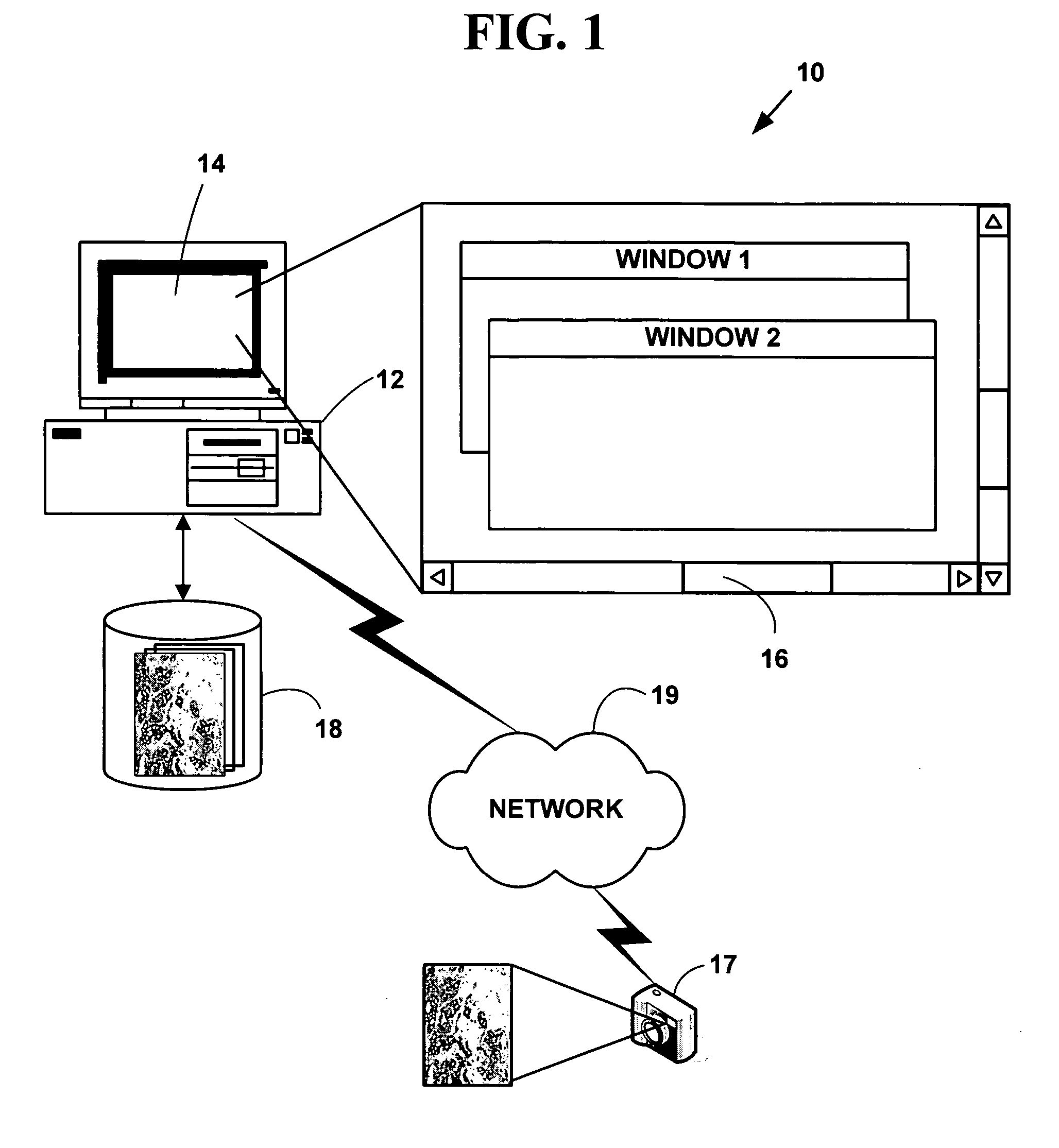
[0079]FIG. 1 is a block diagram illustrating an exemplary biological sample analysis processing system 10. The exemplary biological sample analysis processing system 10 includes one or more computers 12 with a computer display 14 (one of which is illustrated). The computer display 14 presents a windowed graphical user interface (“GUI”) 16 with multiple windows to a user. The present invention may optionally include a microscope or other magnifying device (not illustrated in FIG. 1) and / or a digital camera 17 or analog camera. One or more databases 18 (one or which is illustrated) include biological sample information in various digital images or digital data formats. The databases 18 may be integral to a memory system on the computer 12 or in secondary storage such as a hard disk, floppy disk, optical disk, or other non-volatile mass storage devices. The computer 12 and the databases 18 may also be connected to an accessible via one or mor...
PUM
| Property | Measurement | Unit |
|---|---|---|
| cell size | aaaaa | aaaaa |
| luminance parameters | aaaaa | aaaaa |
| luminance | aaaaa | aaaaa |
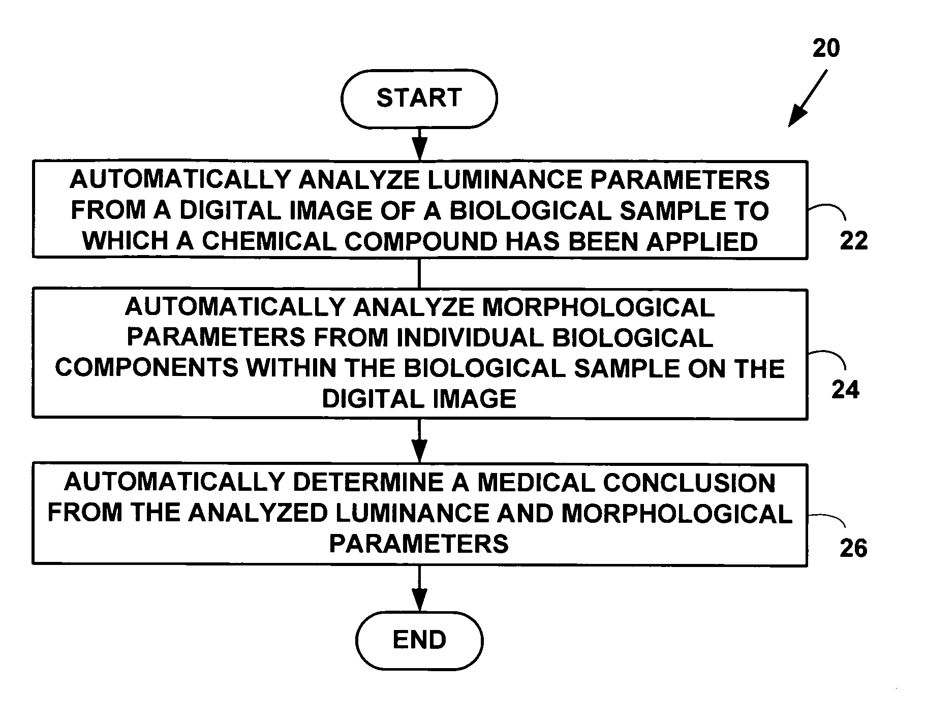
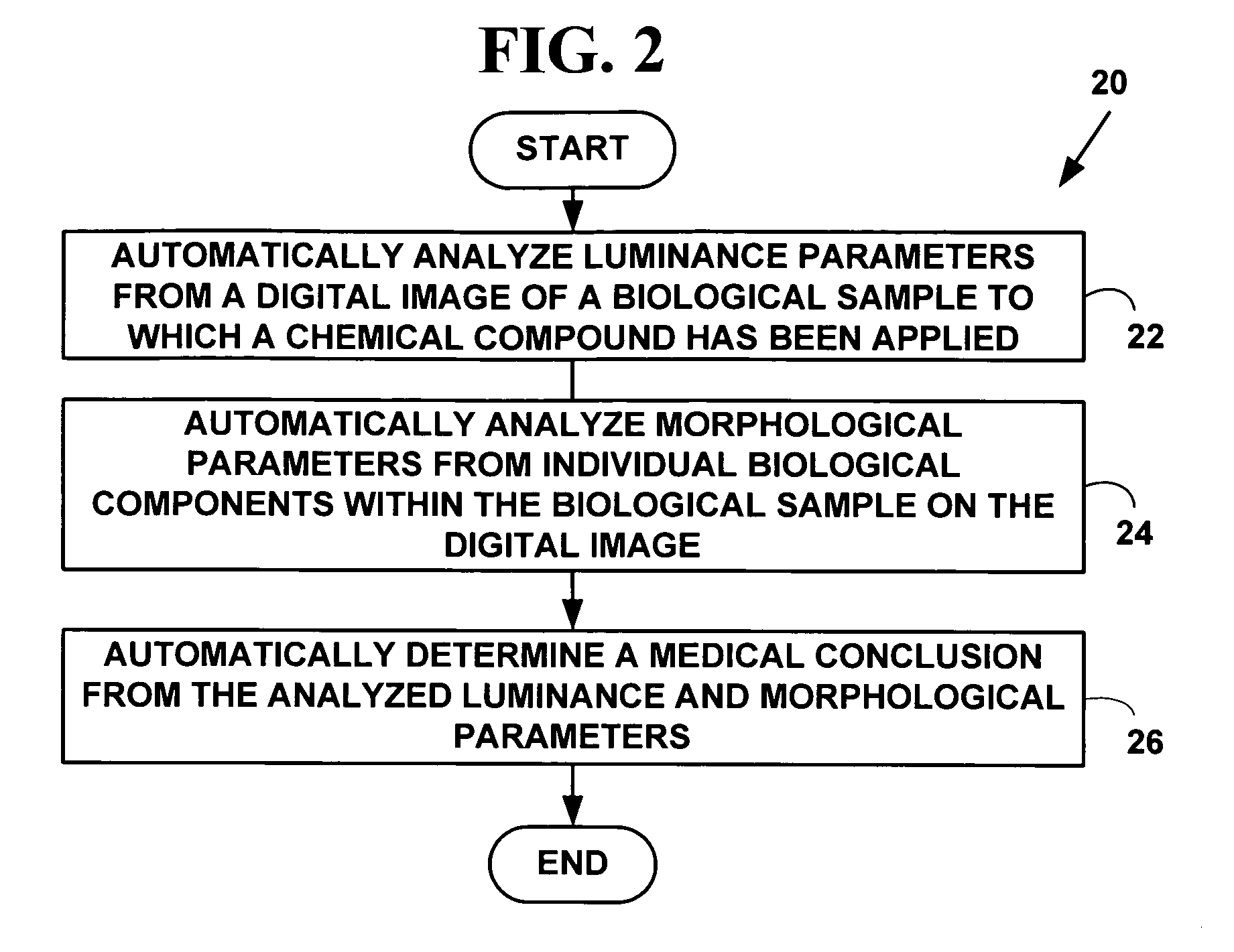
Abstract
Description
Claims
Application Information