Flow control of electrochemical-based assay devices

a flow control and electrochemical technology, applied in the direction of measurement devices, biochemical equipment and processes, instruments, etc., can solve the problems of lowering affecting the sensitivity of the biosensor, and consuming too much time for analyte to adequately mix

Inactive Publication Date: 2005-06-23
KIMBERLY-CLARK WORLDWIDE INC
View PDF99 Cites 108 Cited by
  • Summary
  • Abstract
  • Description
  • Claims
  • Application Information

AI Technical Summary

Problems solved by technology

Unfortunately, conventional flow-through electrochemical biosensors, such as described above, possess various problems.
For instance, such devices require a large sample volume of sample to conduct the assay.
Namely, when the test sample has a low volume (e.g., less than about 100 microliters), it leaves the analyte too little time to adequately mix and react with the desired reagents immobilized on the surface of the detection working electrode, which often leads to inaccurate results.
Moreover, the specific configuration of such conventional biosensors often allows a large portion of the test sample to flow around the edges of or without any contact with the electrode, thereby lowering the sensitivity of the biosensor and increasing the required sample volume size.
In addition, other than the membrane, there are no flow control mechanisms.
On the other hand, if a fast moving membrane (e.g., nylon mesh) is used, the flow speed may be too fast to handle the data acquisition or necessary reaction time.

Method used


Image

  • Flow control of electrochemical-based assay devices
  • Flow control of electrochemical-based assay devices
  • Flow control of electrochemical-based assay devices

Examples


example 1

[0062] Electrodes were printed onto Mylar® substrates obtained from DuPont. The substrates had a width of 1.5 centimeters and a length of 4.5 centimeters. Carbon (7101 or 7102), silver (5000), and silver / silver chloride (5847) inks were obtained from DuPont Biosensor Group of Research Triangle Park, North Carolina. For printing the inks, a screen frame was first fixed onto a screen frame holder and adjusted. Initially, a silver ink line was printed on the substrates to enhance the conductivity between the leads and electrodes to be printed. Thereafter, carbon ink was printed over the silver ink line to form a detection working electrode and a counter electrode. The silver / silver chloride ink was printed onto the substrates to form a reference electrode. Leads for the electrodes were then printed. Insulation of the leads was achieved by printing a layer of UV curable dielectric ink, available from DuPont Biosensor Group under the name “5018G.” The insulation layer essentially covered...

example 2

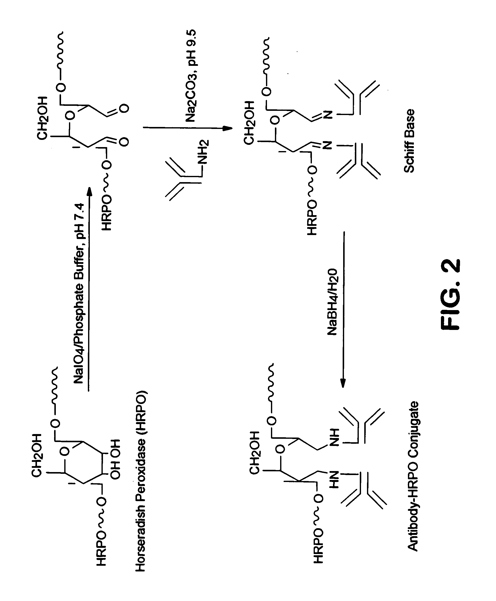
[0063] Membrane strips of a nylon mesh membrane (11 mesh size, commercially available from Millipore Corp. of Billerica, Mass.) were provided that had a width ranging from 3.5 to 4.5 centimeters and a length of 15 centimeters. To the bottoms of the strips, two glass fiber pads (sample and conjugate pads) were attached using tape. The conjugate pad was in direct contact with the membrane, and the sample pad was in direct contact with the conjugate pad. The conjugate pad was treated with 3 microliters of LH-α-HRP monoclonal antibody conjugate (5 micrograms per milliliter in PBS buffer) and dried for 30 minutes. The LH-α-HRP monoclonal antibody conjugate was obtained from Fitzgerald Industries Int'l of Concord, Mass. The membrane strips were placed onto a sampling instrument commercially available from Kinematic Automation of Twain Harte, Calif. under the name “Matrix 2210 (Universal Laminator).” Thereafter, the strips were cut into individual strips having a width ranging from 1 to 10...

example 3

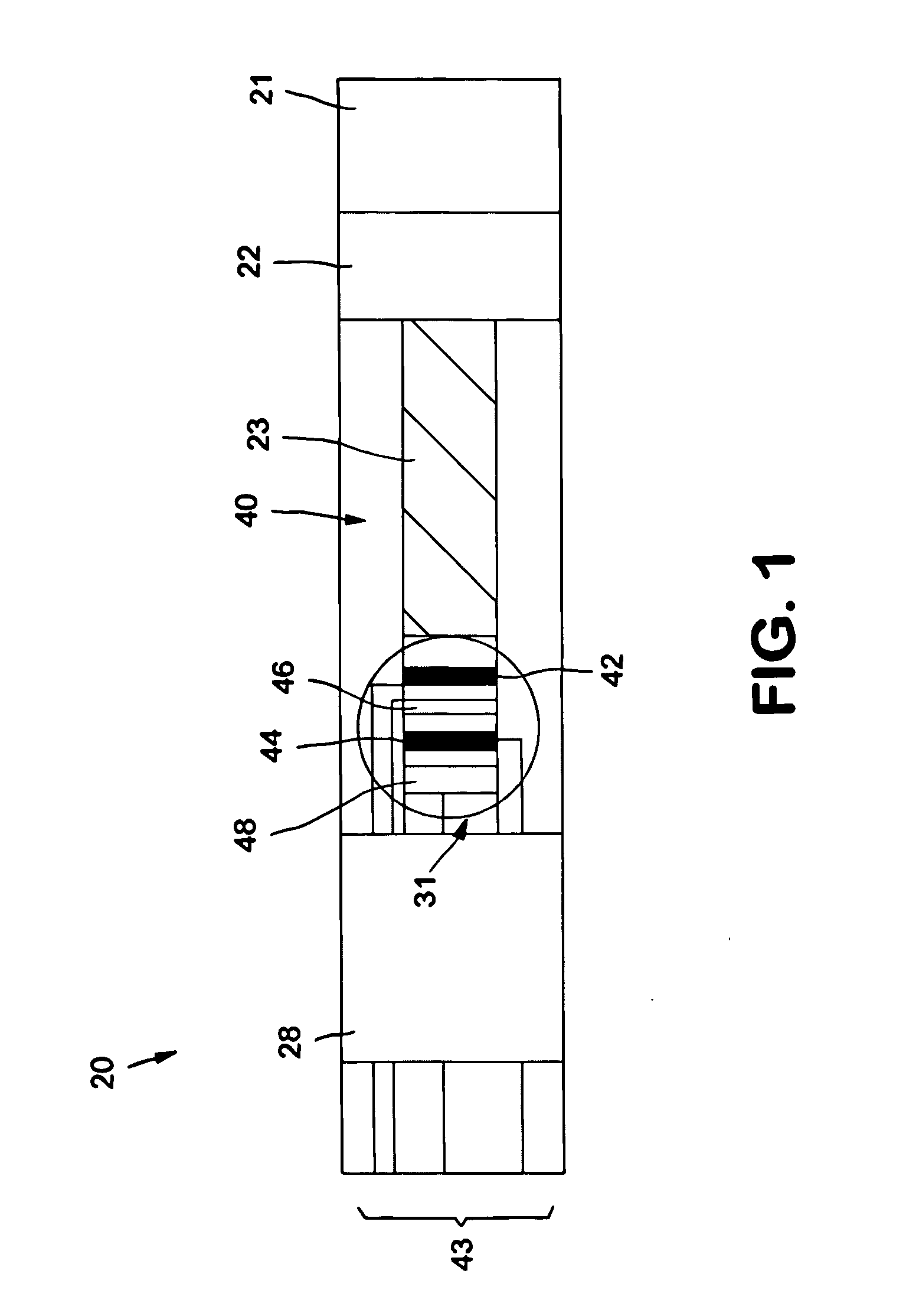
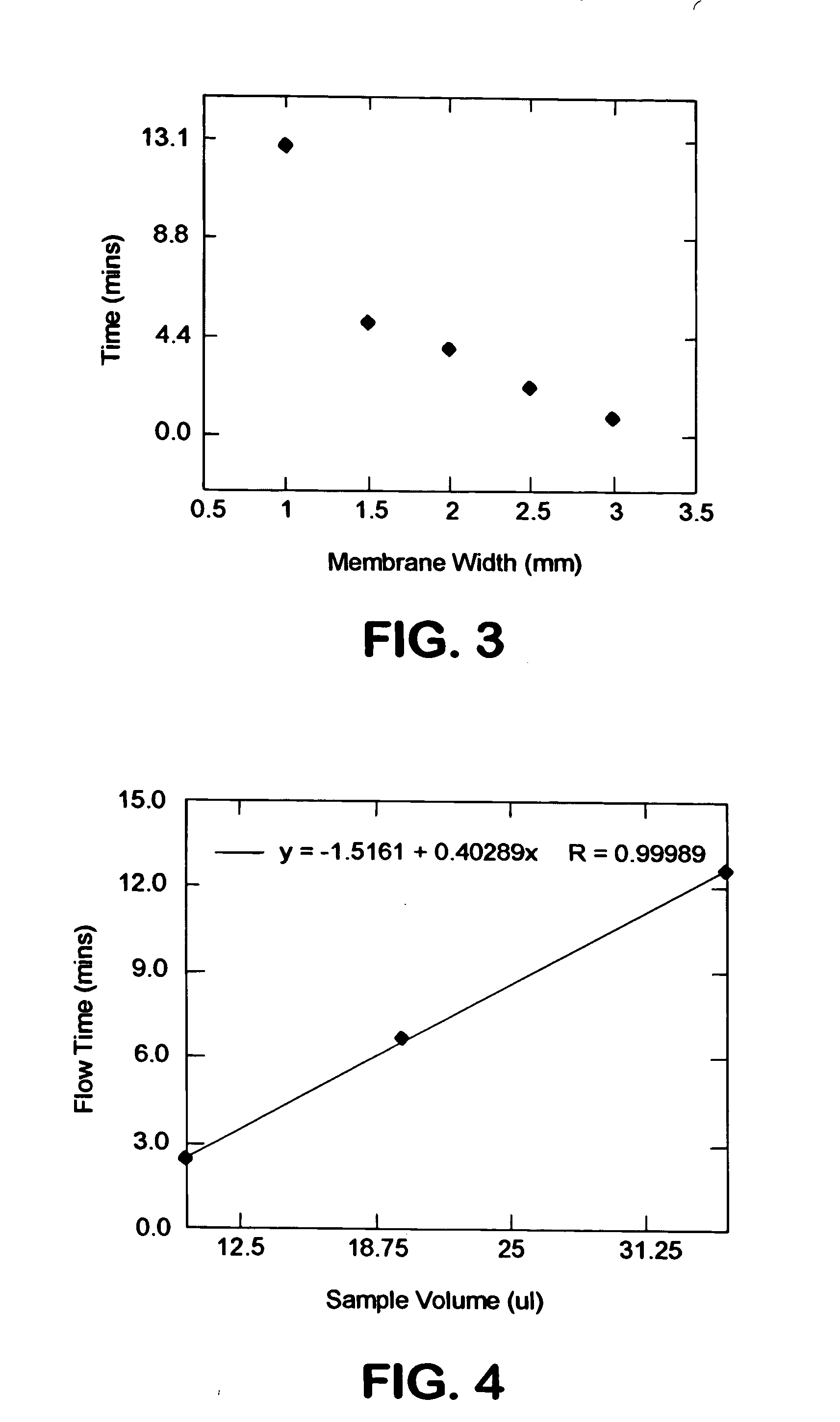
[0064] The ability to control the flow of a test sample in accordance with the present invention was demonstrated. Specifically, membrane strips of Example 2 were provided that had a width ranging from 1 to 3 millimeters. In addition, electrode strips of Example 1 were provided. The membrane strips were attached onto the surface of the electrode strips so that the membrane and electrode strips were parallel. A wicking pad was also attached downstream from the electrodes having a length of 1 centimeter and a width of 1.5 centimeters. The strips and wicking pad were attached using a covering tape that allowed the test sample to flow to the electrodes through a path defined by the membrane. The covering tape had a length of 3 centimeters and a width of 1.5 centimeters, and is commercially available from Adhesives Research, Inc. of Glen Rock, Pa. under the name “ARcare®.” Once formed, a test sample having a volume of 35 microliters was applied to the sample pad of each strip. The test s...


PUM

PropertyMeasurementUnit
volumeaaaaaaaaaa
volumeaaaaaaaaaa
volumeaaaaaaaaaa

Abstract

Various techniques for controlling the flow of a test sample through an electrochemical-based assay device are provided. The assay device contains a porous membrane provided with certain properties to selectively control the flow of a test sample to a detection working electrode. The detection working electrode communicates with affinity reagents, such as redox mediators and capture ligands. For instance, capture ligands that are specific binding members for the analyte of interest are applied to the detection electrode to serve as the primary location for detection of the analyte.

Description

BACKGROUND OF THE INVENTION [0001] Various analytical procedures and devices are commonly employed in assays to determine the presence and / or absence of analytes in a test sample. For instance, immunoassays utilize mechanisms of the immune systems, wherein antibodies are produced in response to the presence of antigens that are pathogenic or foreign to the organisms. These antibodies and antigens, i.e., immunoreactants, are capable of binding with one another, thereby causing a highly specific reaction mechanism that may be used to determine the presence or concentration of that particular antigen in a biological sample. There are several well-known techniques for detecting the presence of an analyte. [0002] One such technique is described in WO 01 / 38873 to Zhang. Zhang describes flow-through electrochemical biosensors designed to detect the presence of an analyte. FIG. 2 of Zhang, for instance, illustrates a sensor assembly 5 that includes an absorbent pad 18, a wicking mesh 22, an...

Claims


Application Information

Patent Timeline
Patent Type & Authority Applications(United States)
IPC IPC(8): C12Q1/54G01N33/543G01N33/558
CPCG01N33/54373
Inventor YANG, KAIYUANHUGHES, CHARLES TRACYSONG, XUEDONGKAYLOR, ROSANN MARIE MATTHEWS
Owner KIMBERLY-CLARK WORLDWIDE INC
Why Eureka
Try Eureka