
Transmitter

Inactive Publication Date: 2005-06-23
PANASONIC CORP
View PDF16 Cites 65 Cited by
  • Summary
  • Abstract
  • Description
  • Claims
  • Application Information

AI Technical Summary

Benefits of technology

[0010] Therefore, with the foregoing in mind, it is an object of the present invention to provide a transmitter having the EER technique whose efficiency at the time of the average power is improved without degrading the maximum output power by controlling a voltage input to a collector terminal or a drain terminal as well as a voltage input to a base terminal or a gate terminal in accordance with a power output from a high-frequency power amplifier so as to set the operating class of the high-frequency power amplifier variably.
[0013] From the above, the voltage input to the collector terminal or the drain terminal as well as the voltage input to the base terminal or the gate terminal can be controlled in accordance with the power output from the high-frequency power amplifier and the operating class of the high-frequency power amplifier can be set variably. Thereby, a transmitter having the EER technique can be provided in which the efficiency at the time of the average power can be improved without degrading the maximum output power.
[0016] From the above, the voltage input to the collector terminal or the drain terminal as well as the voltage input to the base terminal or the gate terminal can be controlled in accordance with the power output from the high-frequency power amplifier and the operating class of the high-frequency power amplifier can be set variably. Thereby, a transmitter having the EER technique can be provided in which the efficiency at the time of the average power can be improved without degrading the maximum output power.
[0017] Furthermore, in the phase / amplitude separation unit in the first transmitter, filtering is conducted with respect to the phase component within a range that is permissible by the band of a digital / analogue converter and in such a degree that does not affect the modulation accuracy adversely. At this time, a partial decrease of the level of the phase component caused by the filtering generates a prominent deterioration of the modulation accuracy of the modulated wave in which the phase component is synthesized with the amplitude component at the output of the high-frequency power amplifier. As compared with the first transmitter, the phase / amplitude separation unit is not used in the second transmitter, and the modulation wave signal from the modulation wave signal generation unit is used as it is as a phase component. Therefore, the deterioration of the modulation accuracy, which inevitably occurs in the EER technique performed by separating the amplitude component and the phase component, can be avoided.
[0020] With this configuration, within the voltage range that includes the voltage level of the amplitude component for outputting the average power, the output voltage from the first voltage conversion unit is made constant, whereby the operating class of the high-frequency power amplifier can be fixed irrespective of the voltage level of the amplitude component, thus minimizing the deterioration of the modulation accuracy and the output waveform due to the fluctuation of the operating class.
[0022] With this configuration, since a desired output power level can be designated for the modulation wave signal generation unit, the output power level can be set freely by setting an IQ level by the modulation wave signal generation unit.

Problems solved by technology

However, in accordance with the migration of communication to broadband, a communication technique such as OFDM (Orthogonal Frequency Division Multiplex) using a multicarrier has started to be used, and a conventional high-frequency power amplifier of the operational class such as class A and class AB has not been expected to provide high efficiency.
As a result, the efficiency deteriorates considerably.
Therefore, in the case of a portable radio using a battery as a power source, for example, the continuous operable time becomes short, thus posing a practical problem.
Therefore, the operating class of the high-frequency power amplifier should be set always at the operating class that enables the output of the required maximum output power, so that even when the average or lower power is output, the operating class of the base terminal or the gate terminal remains as the class A or the class AB close to the class A. As a result, considering an idle current applied to a collector terminal or a drain terminal, more than the necessary amount of the idle current should be fed when the average or lower power is output, which tends to degrade the efficiency in terms of the average power.

Method used


Image

  • Transmitter
  • Transmitter
  • Transmitter

Examples


embodiment 1

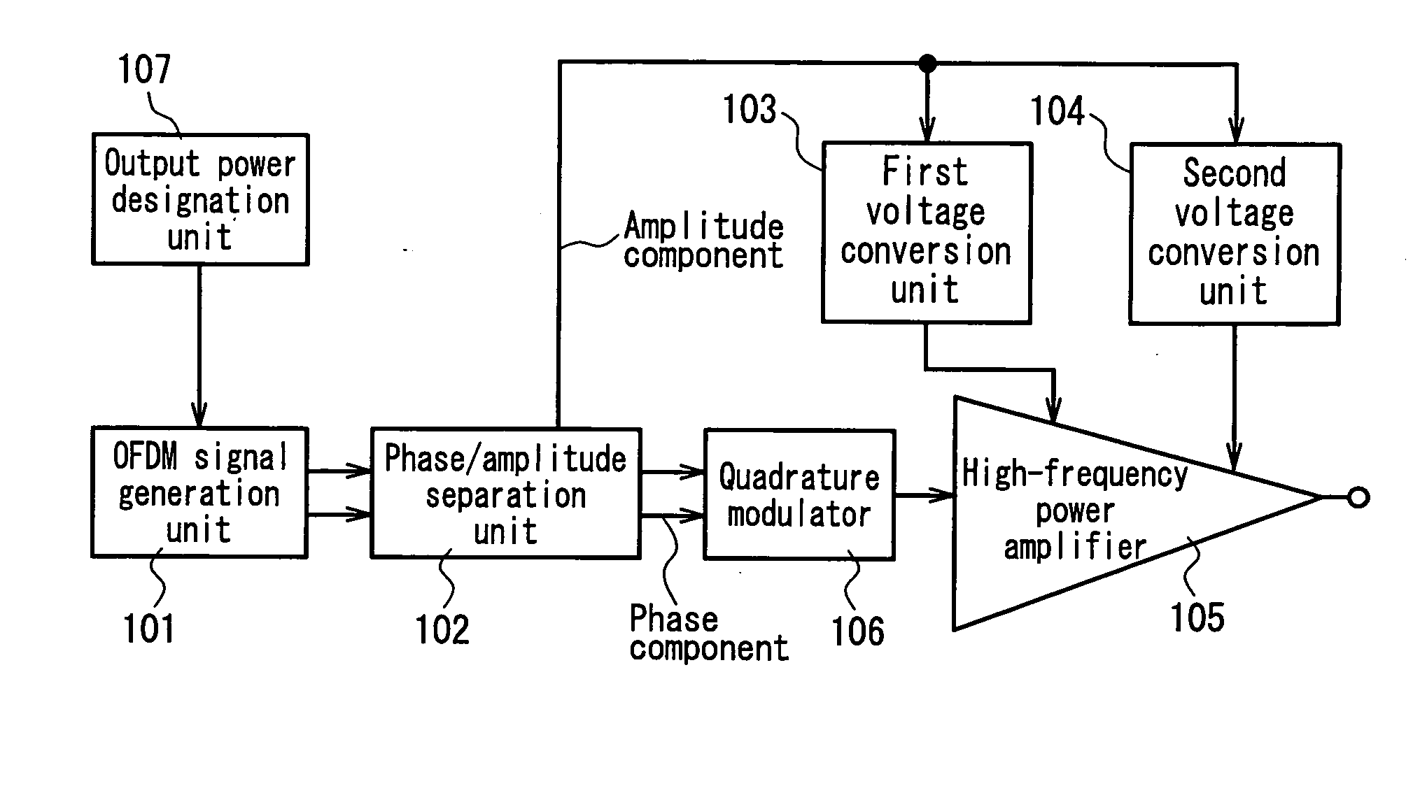
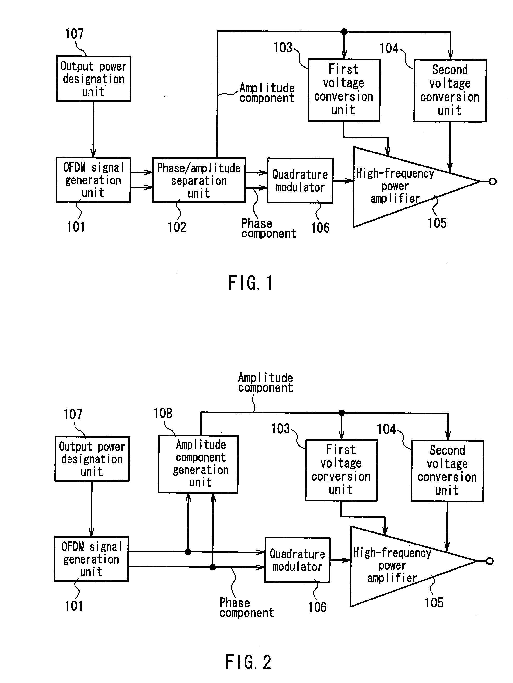
[0033]FIG. 1 is a circuit block diagram showing one exemplary configuration of a transmitter that realizes the EER technique according to Embodiment 1 of the present invention. This transmitter, as shown in FIG. 1, includes: an OFDM signal generation unit 101 as a modulation wave signal generation unit: a phase / amplitude separation unit 102; a first voltage conversion unit 103 and a second voltage conversion unit 104 each receiving an amplitude component from the phase / amplitude separation unit 102 as an input voltage and varying an output voltage level in accordance with a voltage level of the amplitude component; a high-frequency power amplifier 105 having a base terminal or a gate terminal to which an output voltage of the first voltage conversion unit 103 is applied and a collector terminal or a drain terminal to which an output voltage of the second voltage conversion unit 104 is applied; a quadrature modulator 106 as a frequency conversion unit; and an output power designation...

embodiment 2

[0051]FIG. 2 is a circuit block diagram showing one exemplary configuration of a transmitter that realizes the EER technique according to Embodiment 2 of the present invention. Note here that in FIG. 2 the same reference numerals are assigned to the same elements as in Embodiment 1 and their detailed explanations are omitted.

[0052] The transmitter of the present embodiment, as shown in FIG. 2, is different from Embodiment 1 in that a modulation wave signal output from an OFDM signal generation unit 101 is supplied directly to a quadrature modulator 106 and an amplitude component generation unit 108 is used for extracting an amplitude component from the modulation wave signal so as to omit the phase / amplitude separation unit 102.

[0053] According to this configuration, instead of the phase component, the modulation wave signal is used as it is as an input signal of the quadrature modulator 106. Therefore, the deterioration of a modulation accuracy (Error Vector Magnitude: EVM), whic...

embodiment 3

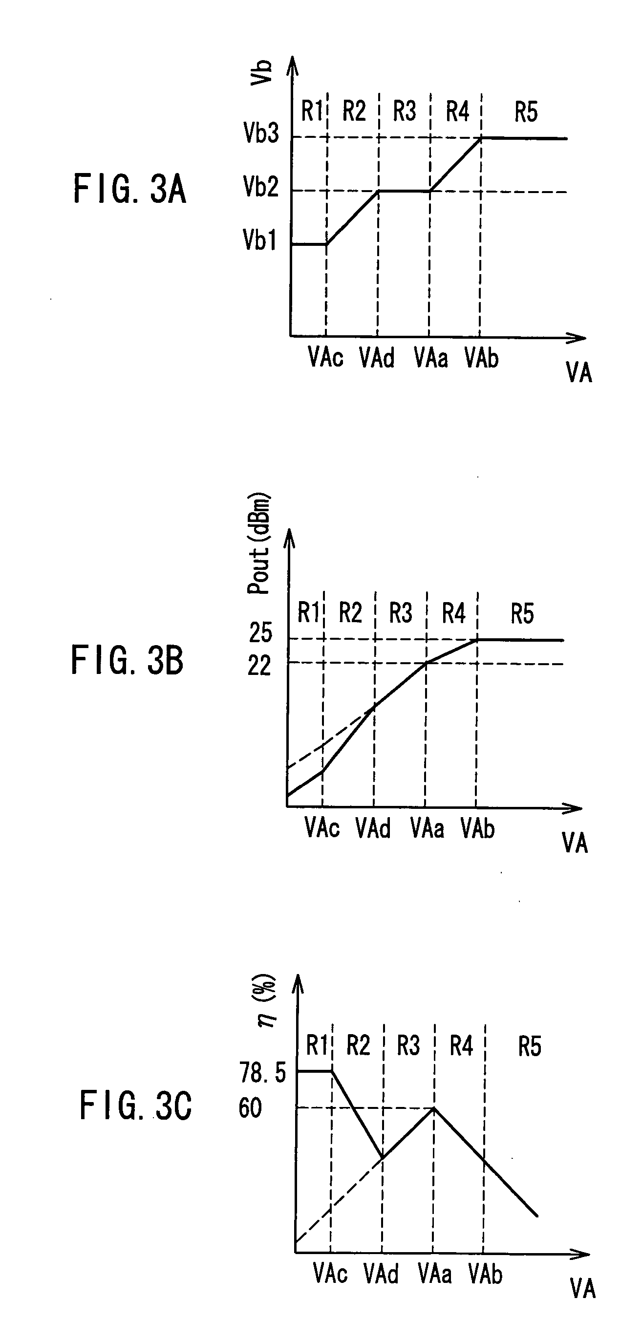
[0061]FIG. 3A, FIG. 3B and FIG. 3C are graphs for explaining a specific exemplary operation of a first voltage conversion unit 103 (FIG. 1 and FIG. 2) of a transmitter according to Embodiment 3 of the present invention. FIG. 4A, FIG. 4B and FIG. 4C are graphs for explaining an operation of a conventional transmitter. In the following description, an operational condition of the conventional transmitter is explained first, and then the operation of the transmitter according to the present embodiment is explained.

[0062] The efficiencies of a high-frequency power amplifier differ as follows depending on the operating classes: under the ideal conditions, the maximum efficiency of the class A operation is 50%, the maximum efficiency of the class B operation is 78.5% and the gain of the class B operation is lower than that of the class A operation by 6 dB. Therefore, consideration is given usually to both characteristics of the efficiency and the gain, and the class AB is selected as the...


PUM


Abstract

In a range (R3) in which an amplitude component voltage (VA) of a modulation wave signal from an OFDM signal generation unit corresponds to the average output power, an output voltage of a first voltage conversion unit (voltage applied to a base or a gate) is fixed, thus allowing the class AB operation of a high-frequency power amplifier. In a range (R4) in which VA is larger than that in R3, the output voltage of the first voltage conversion unit is increased, thus varying the operating class of the high-frequency power amplifier from class AB to class A. In a range (R2) in which VA is smaller than that in R3, the output voltage of the first voltage conversion unit is decreased, thus varying the operating class of the high-frequency power amplifier from class AB to class B. The efficiency at the time of the average power can be improved without degrading the maximum output power of the high-frequency power amplifier included in a transmitter.

Description

FIELD OF THE INVENTION [0001] The present invention relates to a radio transmitter. BACKGROUND OF THE INVENTION [0002] In general, in a modulation signal involving amplitude modulation, especially in multi-valued modulation such as QAM (Quadrature Amplitude Modulation), a linear operation is required for a high-frequency power amplifier that transmits an electric power to an antenna. For that reason, class A or class AB has been used as the operating class of the high-frequency power amplifier. [0003] However, in accordance with the migration of communication to broadband, a communication technique such as OFDM (Orthogonal Frequency Division Multiplex) using a multicarrier has started to be used, and a conventional high-frequency power amplifier of the operational class such as class A and class AB has not been expected to provide high efficiency. That is, in the OFDM, a large electric power occurs instantaneously and completely at random due to the superposition of subcarriers, and...

Claims


Application Information

Patent Timeline
IPC IPC(8): H03G3/30H04B1/02H04B1/04H04L27/26H04L27/36H05B41/16H05B41/24
CPCH04L27/2626H04L27/2614
Inventor AKIZUKI, TAIJITANABE, MITSURUTANAKA, KOICHIRO
Owner PANASONIC CORP
Learn More