Magnetic bearing system

a bearing system and magnetic technology, applied in the direction of sliding contact bearings, machines/engines, liquid fuel engines, etc., can solve the problems of increasing the rotation speed and prolonging the life of the rotating machine and its bearing system, and achieve the effect of eliminating radial large-area friction and being easy to assembl

Inactive Publication Date: 2005-06-30
DELTA ELECTRONICS INC
View PDF5 Cites 35 Cited by
  • Summary
  • Abstract
  • Description
  • Claims
  • Application Information

AI Technical Summary

Benefits of technology

[0011] The invention is easily to assemble. Besides, it eliminates the radial large-area friction between a shaft and a bearing and the noise resulted thereof, and it also elongates the life of rotating machines and bearings.

Problems solved by technology

This usage effectively reduces the friction, noise and vibration produced during an operation of a rotating machine, and thus increases rotating speed and prolongs the life of the rotating machine and its bearing system.

Method used


Image

  • Magnetic bearing system
  • Magnetic bearing system
  • Magnetic bearing system

Examples


Embodiment Construction

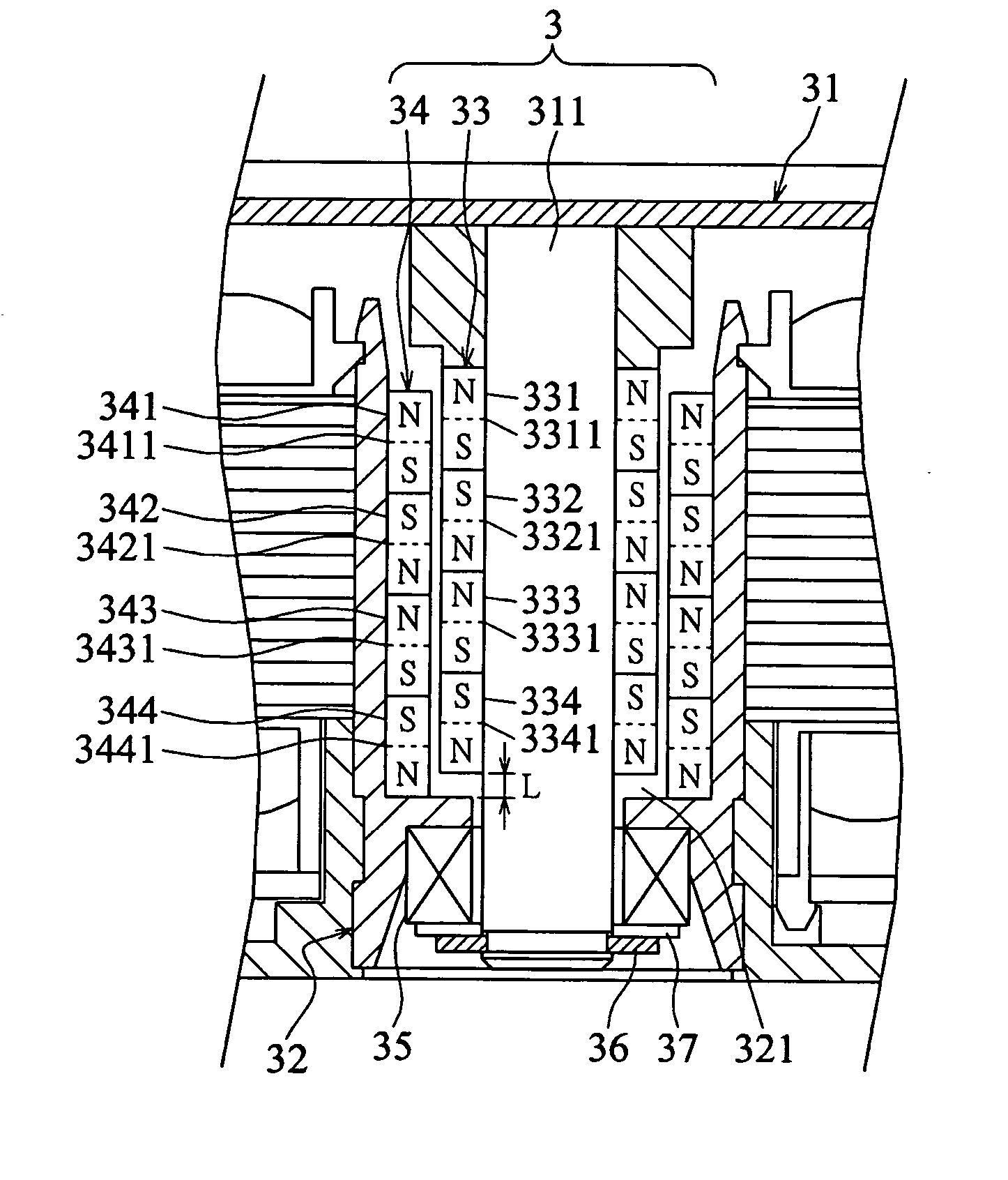
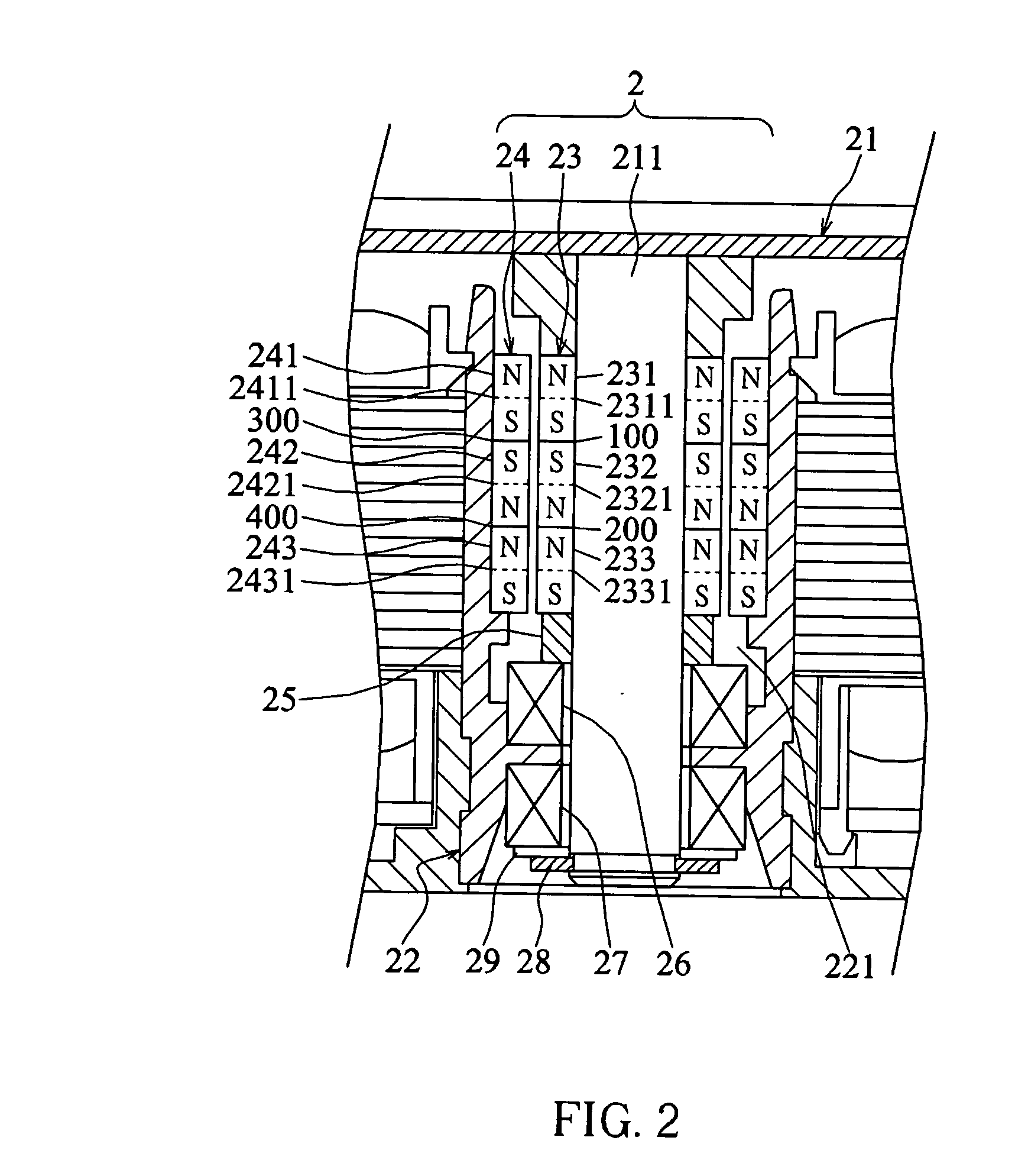
[0022] Referring to FIG. 2, a magnetic bearing system 2 according to the first aspect of the invention is a stacked passive magnetic bearing system made of two magnetic assemblies 23 and 24 for providing radial support. Each of the magnetic assemblies 23 and 24 has more than one magnets stacked with the same-polarity ends jointed together, and the two assemblies are mounted separately on a shaft 211 and a stator seat 22 of the magnetic bearing system 2. The magnets can be annular conducting magnets or annular permanent magnets, and the annular permanent magnets are used to illustrate and describe the following embodiments of the invention.

[0023] The first magnetic assembly 23 is made of stacked annular permanent magnets 231, 232, and 233 with the same polarity of these magnets jointed together at joint faces 100 and 200 (North to North and South to South), and is mounted around the shaft 211 on a rotor 21 of a fan motor. The second magnetic assembly 24 is also made of stacked annul...


PUM


Abstract

A magnetic bearing system for a rotating machine is disclosed. The magnetic bearing system provides a non-contacting radial rigid support for the rotating machine by employing two magnetic assemblies each being formed by stacked annular magnets. The magnetic assemblies are mounted separately on a shaft of the rotating machine and a shaft hole provided on the stator seat of the rotating machine for containing the shaft.

Description

BACKGROUND OF THE INVENTION [0001] (a) Field of the Invention [0002] This invention relates to a bearing system for a rotating machine and, more specifically, to a magnetic bearing system. [0003] (b) Description of the Related Art [0004] Oil-retaining bearings and ball bearings, for today's rotating machines, are commonly used to provide a shaft with radial support and free rotation. However, the decrease of the oil quantity contained in an oil-retaining bearing due to long-term usage of the machine or poor sealing of the system can increase the friction force between the oil-retaining bearing and the shaft and results in accompanied high-temperature and noise. Therefore, oil-retaining bearings are becoming less capable of satisfying the requirements of high-performance rotation machines. On the other hand, ball bearings have a problem of wear variation for each rolling ball and thus cause unexpected vibration of the motor during operation and, in turn, produce big noise. [0005]FIG....

Claims


Application Information

Patent Timeline
Patent Type & Authority Applications(United States)
IPC IPC(8): F04D25/06F04D29/058F16C17/08F16C19/12F16C32/00F16C32/04F16C39/06H02K7/08H02K7/09
CPCF04D29/058F16C17/08F16C19/10F16C19/163F16C19/30F16C2360/46F16C32/0425F16C39/063H02K7/085H02K7/09F04D25/062F16C32/0402F16C2380/26
Inventor YEH, TING-JENCHUANG, KUN-FUHUANG, WEN-SHI
Owner DELTA ELECTRONICS INC
Why Eureka
Try Eureka